
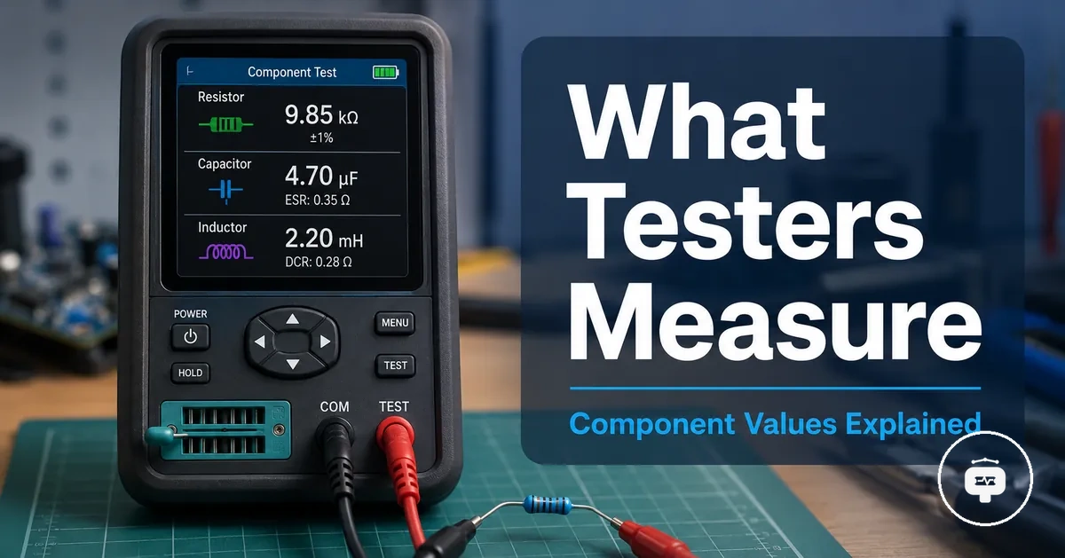
What Electronic Component Testers Measure and Identify
An electronic component tester is a measurement tool that identifies a connected component and provides measurement information about its electrical characteristics. It can identify components such as a resistor, capacitor, transistor, or diode while linking component identification with measurement.
Depending on the tester design and measurement method, the displayed value may include the detected component type together with one or more measured characteristics. Automatic detection can simplify component identification, but its capability depends on the tester design, supported component types, measurement method, and the condition of the component being tested.
An electronic component tester reports measured characteristics rather than confirming every real-world failure mode. Its measurements can support component identification and evaluation, but complete diagnosis may require additional testing within the component's operating context.
What an Electronic Component Tester Does
An electronic component tester is a measurement tool that tests electronic parts by identifying their component type and measuring selected electrical characteristics. Its core purpose is to identify a component and present measurement results through a value display.
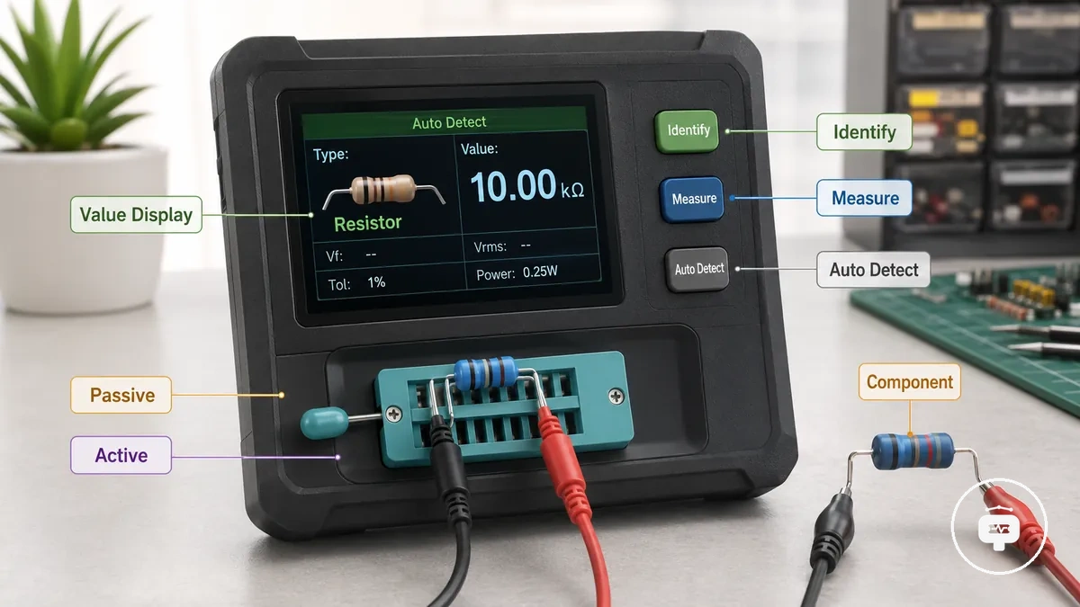
An electronic component tester can test both a passive component and an active component, depending on the tester design and supported measurement functions. Automatic detection may identify the component type before the tester measures its electrical characteristics and presents the results on the value display. The available measurements and displayed information depend on the tester design, measurement method, and the connected component. Different tester designs provide different measurement capabilities, as explained in tester types explained.
Automatic detection can simplify component identification, but capability remains dependent on the tester design and the components it supports. An electronic component tester provides measurement information that can assist evaluation, although complete fault diagnosis may require additional testing under operating conditions.
How Electronic Component Testers Identify Parts
Electronic component testers identify parts by measuring their electrical characteristics and matching those measurements with recognised component patterns. Automatic identification is based on measured electrical behaviour rather than visual appearance, linking component recognition to measured characteristics.
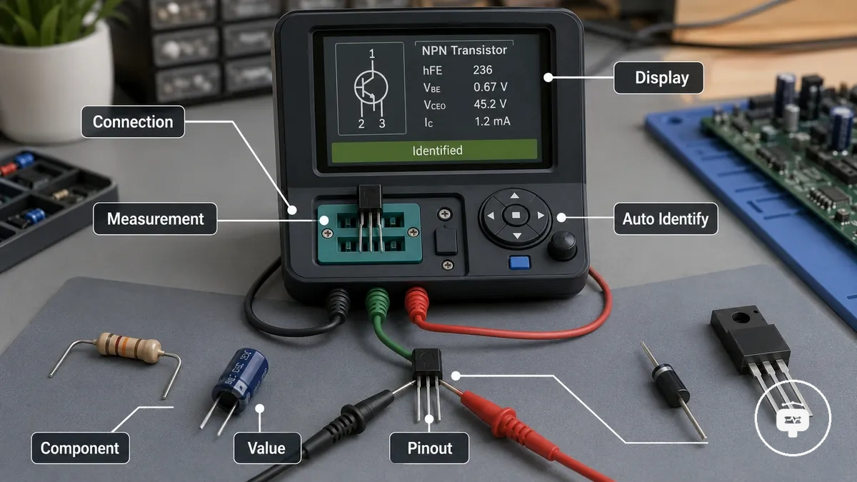
When a part is connected, the tester evaluates its electrical characteristics to support component recognition. The measured response may allow the tester to identify a resistor, capacitor, diode, transistor, or another supported component type. If identification is successful, the display can present the recognised component together with information such as pinout and measured value. The available readout depends on the tester capability, the measurement method, and the connected part. These identification concepts provide context for practical operation, which is covered in basic tester workflow.
Automatic identification depends on tester capability and component condition. Unknown, damaged, or unsupported parts may not be recognised correctly, and electrical identification should not be confused with visual PCB component identification or treated as a complete diagnosis.
Electrical Measurements Electronic Component Testers Provide
Electronic component testers provide electrical measurements that help identify a component type and present its measured characteristics through a value display. The available readings depend on the tester design and measurement range, with the main categories covering passive component measurements and semiconductor-related identification.
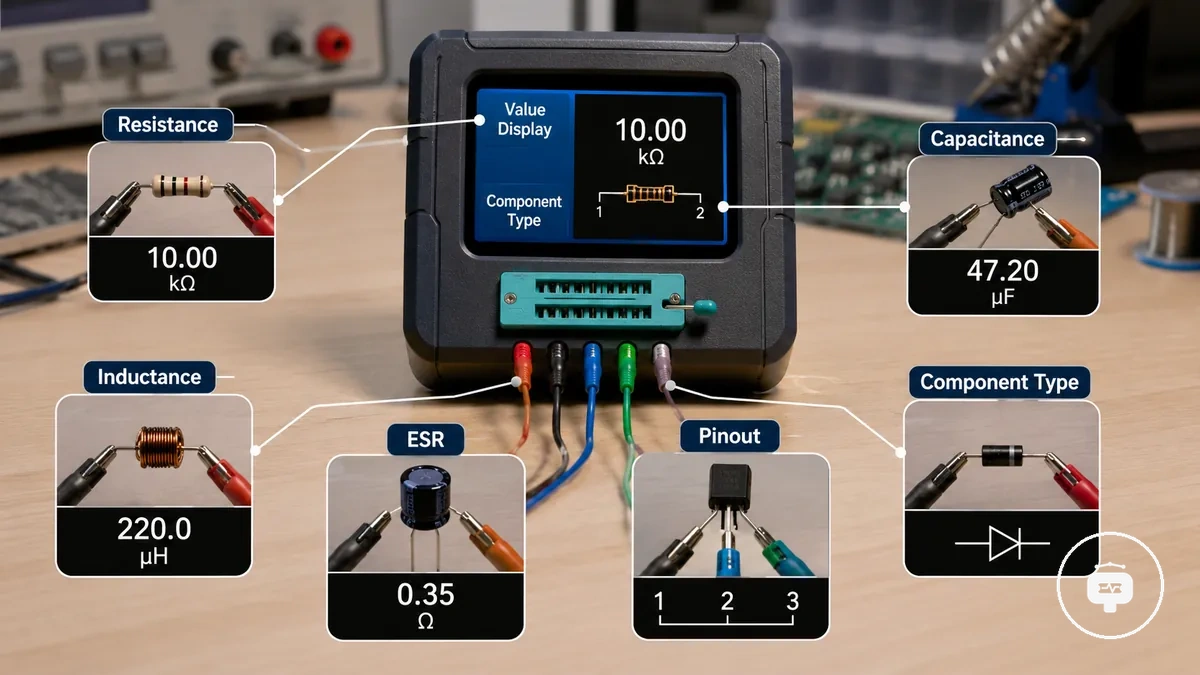
For passive components, the tester may display resistance for a resistor, capacitance for a capacitor, and inductance for supported inductive components. Some tester designs may also report ESR to provide additional information about capacitor condition alongside its capacitance reading. These displayed values help interpret measured electrical parameters but do not, by themselves, confirm the overall condition of a component. The available measurement categories depend on the supported component type, as discussed in components they can test.
For semiconductor components, the tester may identify a diode or transistor and display information such as pinout together with measured electrical parameters. The displayed values depend on the detected component type, the measurement range, and the tester design. These readings support component identification and interpretation, but they should not be treated as a guaranteed diagnosis.
Measurement range and supported electrical measurements vary between tester designs. As a result, the available displayed values and measurement capabilities depend on both the tester and the connected component.
Resistance, Capacitance, and Inductance Measurements
Resistance, capacitance, and inductance measurements describe the primary electrical properties of a passive component. A displayed value helps interpret the measured characteristic of a resistor, capacitor, or inductor. These passive measurements are grouped as resistance, capacitance, and inductance.
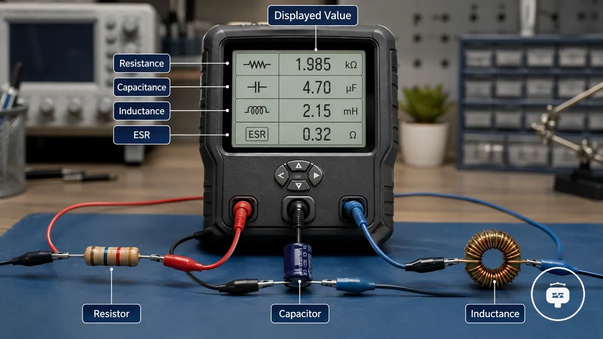
A resistor is measured by its resistance, with the displayed value typically shown in ohms to indicate the measured value. A capacitor is measured by its capacitance, and some tester designs may also display ESR to provide additional context alongside the capacitance reading. An inductor, when supported by the tester design and supported range, can display its inductance as a measured value. Low-value, damaged, or out-of-range passive components may produce limited or unavailable readings, depending on the tester design.
Semiconductor Identification and Component Characteristics
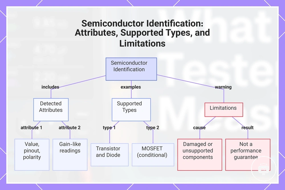
Semiconductor identification recognises supported semiconductor parts from their detected electrical characteristics. The displayed information may include a detected value together with attributes such as pinout or polarity, depending on the tester design. This local measurement function focuses on semiconductor identification rather than complete performance evaluation.
A transistor may be identified from its detected pinout and displayed device characteristics, while available gain-like readings depend on the tester design. A diode may be recognised from its junction behaviour and polarity, with the detected value helping interpret the displayed reading. A MOSFET may also be detected when the tester supports that semiconductor type, although gate-related detection and displayed characteristics vary by tester design and component condition. If a semiconductor is damaged, unsupported, or its electrical characteristics cannot be recognised reliably, the tester may not identify it correctly, so identification should not be treated as confirmation of full operating performance.
This chart shows what semiconductor identification detects, which component types it supports, and its key limitations.
Components Commonly Tested by Electronic Component Testers
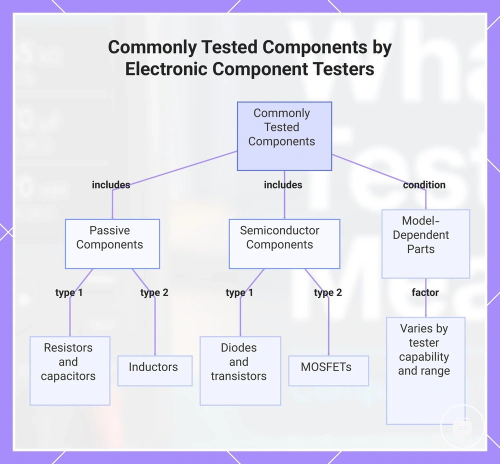
Electronic component testers commonly measure and identify supported components such as resistors, capacitors, diodes, transistors, inductors, and MOSFETs. The components tested depend on the tester capability and its measurement range. These main component groups include passive components and semiconductor components.
Passive components such as resistors, capacitors, and inductors are measured through their electrical characteristics, while semiconductor identification focuses on supported components such as diodes, transistors, and MOSFETs. The available readings and identification results depend on the tester capability, supported components, and measurement range rather than a fixed feature set. Different tester designs may support additional component groups, but this overview focuses on the most common supported parts and their relationship to measurement functions. For broader compatibility information, see components they can test.
- Passive components: Resistors, capacitors, and inductors measured through electrical values such as resistance, capacitance, and inductance.
- Semiconductor components: Diodes, transistors, and MOSFETs identified through detected electrical characteristics such as polarity, pinout, or related device characteristics.
- Model-dependent supported parts: Additional supported components may vary according to tester capability and measurement range.
This overview describes common supported components rather than a complete compatibility reference because supported parts vary between tester designs.
This chart shows the main component groups tested by electronic component testers, including passive and semiconductor components, and how supported parts depend on tester capability.
Resistors, Capacitors, Diodes, and Transistors Testing
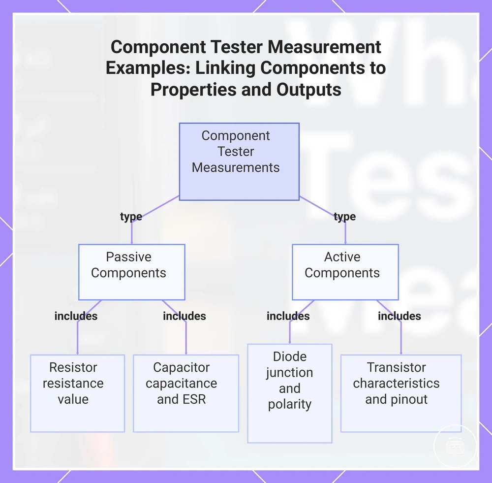
A component tester can demonstrate how common electronic parts relate to specific measurements by linking each tested component to its measured property and possible displayed information. These representative examples show how measurement outputs may vary with tester design while illustrating the relationship between a component and its reading.
- Resistor: The measured property is resistance, and the displayed information may show a resistance value.
- Capacitor: The measured property is capacitance, and the displayed information may include a capacitance reading and, on supported tester designs, an ESR value.
- Diode: The measured property is junction behaviour, and the displayed information may indicate polarity together with a related reading.
- Transistor: The measured property is device characteristics, and the displayed information may include pinout identification together with other recognised characteristics.
The displayed information for a tested component depends on the component tester, its measurement functions, and the recognised component, so these examples remain illustrative rather than definitive.
This chart shows how a component tester links each electronic part to its measured property and possible displayed information.
What Component Tester Readings Reveal
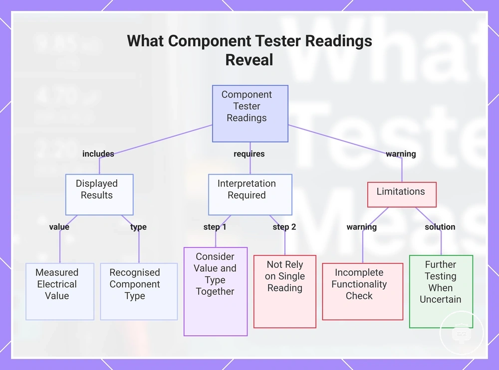
Component tester readings show the measured results detected for a connected component. Displayed results may include a measured value, a recognised component type, or identification details such as pinout, depending on the measurement performed. These readings provide useful information, but they still require interpretation.
A displayed value represents the measured electrical characteristic of the tested component, while the displayed component type indicates what the measurement has recognised. For supported semiconductor components, the displayed results may also include pinout information or other detected characteristics that assist interpretation. The available readings depend on the tester design, measurement function, and recognised component. Interpreting the displayed results involves considering the measured value together with the identified component type rather than relying on a single reading alone.
Measurements can help assess component condition, but they do not always confirm complete functionality or identify every failure mode. Further testing may be needed when the displayed results are incomplete, uncertain, or influenced by the condition of the tested component.
This chart shows the types of results displayed by component testers, how to interpret them, and their limitations for assessing component condition.
What Electronic Component Testers Cannot Determine
Electronic component testers cannot determine every aspect of a component condition from measurement alone. Tester capability is limited to the information obtained through supported measurements and automatic detection. This limitation boundary means a useful measurement result is not the same as a complete assessment of component condition.
The comparison between detectable measurements and conditions outside the tester's scope helps define what a component tester can and cannot confirm. A tester may identify a component type, display a measured value, or provide detected information such as pinout for a supported transistor. In contrast, it cannot confirm whether a damaged component will operate correctly in its intended circuit context because surrounding components and operating conditions may influence the measurement. Automatic detection provides useful results, but it does not replace further testing when the component condition remains uncertain.
| Tester Capability | Limitation | Practical Implication |
|---|---|---|
| Measures electrical characteristics and identifies supported component types | Cannot determine complete component condition | Interpret the measurement together with additional evaluation when needed |
| Provides automatic detection and displayed results | May not show every fault or behaviour in circuit context | Further testing may be required when the reading is incomplete or uncertain |