Electronic Component Tester Connection Methods for Probes and Sockets
Electronic component tester connection methods are the physical interfaces that connect tester terminals to component leads or contact points. A connection method does not define the tester's measurement capability, but it affects how the component is presented to the tester. Probes, sockets, clips, and tweezers support different package shapes and access conditions.
A loose leaded component may fit directly into a ZIF socket when its leads align with the socket contacts and receive suitable contact pressure. Probe leads or test clips provide a flexible connection when lead spacing or access makes direct socket placement impractical, while SMD tweezer probes can reach the terminals of small surface-mount parts. Loose grip, poor pin alignment, limited pad access, or unsteady hand pressure may reduce contact quality and affect the reliability of readings.
The connection method that matters is the one that matches the component package, available contact point, and required stability. Understanding how each interface creates contact provides the basis for choosing between a socket, probe, clip, or tweezer.
What Probe, Socket, and Clip Connections Do in Component Testing
Probe, socket, and clip connections create electrical contact between tester terminals and component leads or pads. Each connection type reaches a contact point in a different way while serving the same basic function. Stable contact helps the tester receive a consistent electrical signal for component identification and measurement.
The image below shows how probe, socket, and clip connections create electrical contact between a tester and a component.
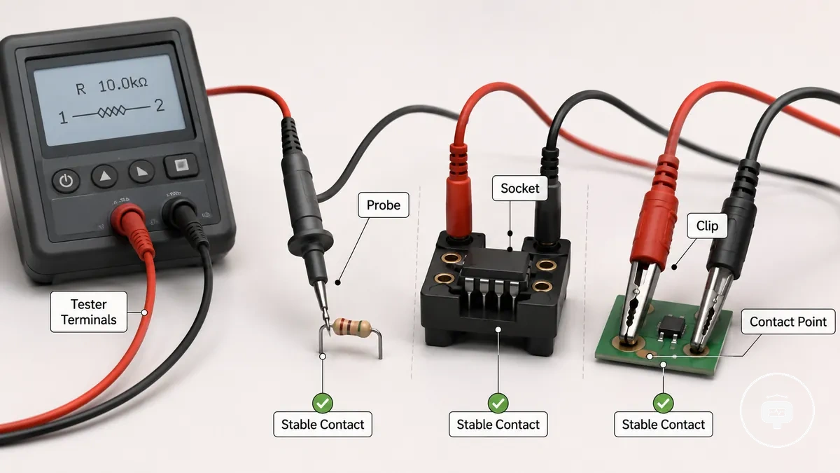
A connection method does not by itself determine the tester's supported component range. The electronic component testers hub introduces the broader category of component testers, while this section focuses on how connections establish electrical contact. When stable contact is maintained at the correct contact point, identification, pinout detection, or measured values may be more consistent, depending on component fit and tester design.
The three connection roles can be summarised as follows:
- Probe connection: Uses a test lead to reach an exposed contact point on component leads or pads.
- Socket connection: Holds component leads in fixed terminal contacts to maintain stable contact.
- Clip connection: Uses a test clip to grip accessible component leads or pads where a flexible connection is more suitable.
ZIF Sockets and Socket Adapters for Leaded Components
ZIF sockets and socket adapters are connection options designed to hold leaded components so their leads align with tester terminals. A ZIF socket applies contact pressure after the component is positioned, helping maintain pin alignment without forcing the leads into the contacts. This connection method is primarily intended for loose leaded components whose lead spacing and package shape fit the socket.
The image below shows how ZIF sockets and socket adapters improve physical fit by aligning leaded components with the tester contacts.
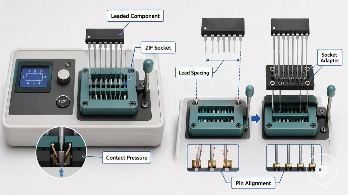
When lead spacing or package shape differs from the standard socket layout, a socket adapter may improve physical fit by changing how the component is positioned. For example, many resistors, capacitors, and transistors can be placed directly when their component leads match the socket, while wider packages may require an adapter socket for improved pin alignment. Stable detection may improve when contact pressure and lead alignment remain suitable for the connection.
Physical fit depends on lead spacing and package shape, so the comparison below focuses only on connection choices rather than tester capability.
| Connection option | Best-fit component shape | Fit condition | Main limitation |
|---|---|---|---|
| ZIF socket | Loose leaded components | Matching lead spacing with suitable contact pressure | Limited by package shape and pin alignment |
| Socket adapter | Wider or different package shapes | Correct adapter fit and pin alignment | Does not make every package compatible |
| Direct lead placement | Components that already fit the tester socket | Accurate lead placement and alignment | Less suitable when spacing or package shape differs |
Physical socket fit does not determine the tester's supported components. Socket fit is limited by lead spacing, package shape, contact pressure, and pin alignment, while overall compatibility also depends on the tester's supported component range.
Lead Placement and Contact Pressure in ZIF Sockets
When component leads reach the correct insertion depth and remain properly aligned, the ZIF socket can maintain suitable contact pressure across the contact area. Correct lead placement helps the socket grip the component leads consistently. The image below compares correct and incorrect lead placement to show how lead position and contact pressure influence socket contact.
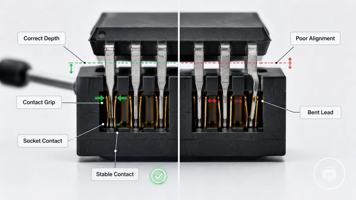
Check lead placement and contact pressure before measurement to reduce poor socket contact.
- Insert the component leads to an appropriate insertion depth.
- Confirm the component leads are aligned with the socket contacts.
- Ensure the contact grip is secure without forcing the leads.
- Inspect for bent, oxidized, or short leads that may reduce contact even when the component type is supported.
A stable reading is more likely when lead placement, contact pressure, and alignment remain suitable, although contact quality may be only one factor affecting reading stability.
Socket Adapters for Transistors, ICs, and Wider Packages
Socket adapters help when a transistor, IC, or wider package does not sit cleanly in the tester's default socket area. Their usefulness depends on pin spacing, pin count, and the tester terminal layout so the package can achieve suitable physical fit and pin alignment. The image below shows how a socket adapter aligns wider packages with the tester terminals when these fit conditions are met.
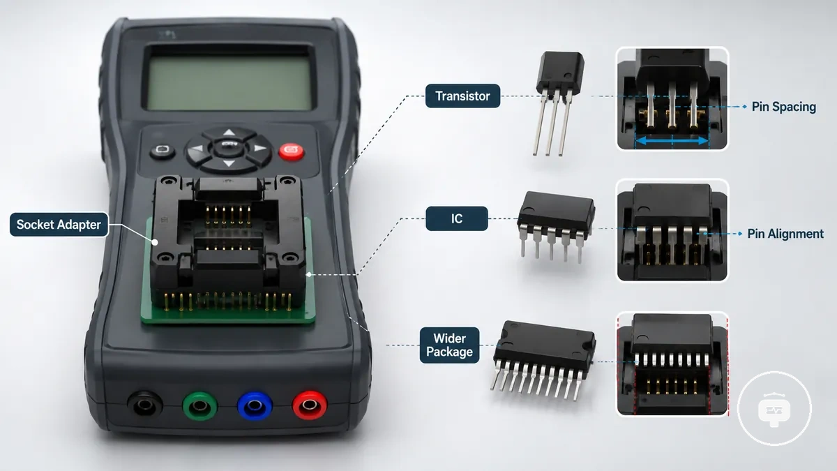
Adapter usefulness depends on pin spacing, pin count, and the tester terminal layout, so the comparison below focuses on physical fit rather than measurement capability.
| Package example | Adapter condition | Fit risk | Support boundary |
|---|---|---|---|
| Transistor | Pin spacing matches the adapter socket | Poor pin alignment | Physical fit only |
| IC | Pin count matches the terminal layout | Misaligned pins | Physical fit only |
| Wider package | Adapter supports the package shape | Uneven contact | Physical fit only |
When a package does not align with the tester socket, a socket adapter may improve the possibility of a reliable connection by improving physical fit and pin alignment. The tester's supported components still determine whether the component can be evaluated, so an adapter does not expand measurement capability. Physical fit and actual component support remain separate conditions.
Probe Leads, Hooks, and Test Clips for Flexible Connections
Probe leads, hooks, and test clips are flexible connections used when a component cannot or should not be placed directly into the tester socket. Each accessory uses a different contact style to reach exposed leads or terminals, while hold stability depends on how securely the connection is maintained. Flexible contact is useful when direct socket placement is impractical because of access or lead position.
When loose components have awkward lead spacing or only require temporary contact, flexible connections can make testing easier. Probe leads provide direct point contact, while hooks and test clips can hold exposed leads with less hand pressure. Movement, grip, and contact surface may still influence reading reliability. The convenience of flexible connections is often balanced against greater contact variability than a well-fitted socket connection.
The comparison below shows how probe leads, hooks, and test clips differ by contact style and hold stability rather than by product type.
| Connection accessory | Contact style | Stability benefit | Main caution |
|---|---|---|---|
| Probe leads | Direct point contact | Flexible positioning | Hand movement may affect contact |
| Hooks | Hooked lead attachment | Hands-free hold | Grip depends on lead shape |
| Test clips | Clamped contact | Improved hold stability | Contact quality depends on grip and contact surface |
Clips or hooks are useful when temporary contact is needed without placing the component into the tester socket. For practical guidance on using probes and sockets, choose the connection method that matches the component and access conditions. Reading reliability may still depend on contact quality, grip, movement, and the contact surface.
Probe Lead Length, Cable Termination, and Connector Fit
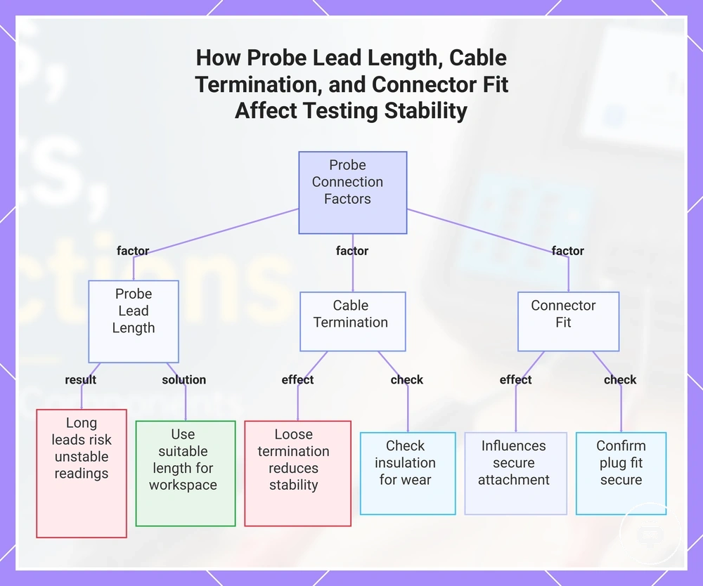
When probe lead length is greater than needed or cable termination is loose, reaching difficult contact points may become easier but handling can become less stable. Probe lead length affects how easily the lead moves during testing, while connector fit influences how securely the lead remains attached to the tester. Practical connection quality depends on suitable lead length, secure connector fit, and controlled handling.
Check probe lead length, cable termination, and connector fit before testing.
- Confirm the plug fit is secure.
- Inspect the insulation for visible wear or damage.
- Use a probe lead length that suits the available working space.
Long or loose leads may increase the chance of unstable readings because movement can change the contact point during handling. Any measurement influence depends on the tester model, component range, and how securely the connection is maintained.
This chart shows the three key factors—probe lead length, cable termination, and connector fit—and their effects on testing stability, along with recommended checks and outcomes.
Hook Clips and Alligator Clips for Holding Leads Steady
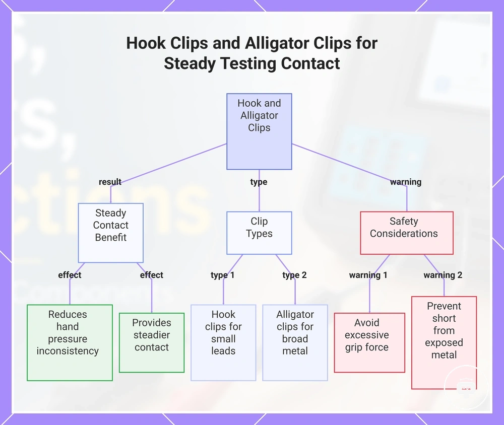
When hand pressure makes contact inconsistent, hook clips and alligator clips can hold component leads in place to provide steadier contact during testing. Hook clips attach to smaller leads with a focused grip, while alligator clips grip a broader exposed metal area. Steady contact matters because movement at the contact point can make temporary connections less consistent.
Use only enough grip to hold the component leads securely. Excessive force may bend or damage small leads, while exposed metal from the clip can create a short risk if it touches unintended conductors. Connection safety still depends on the circuit state, the amount of exposed metal, and the clip position.
This chart shows how hook clips and alligator clips help hold leads steady, their different uses, and key safety warnings.
SMD Tweezer Probes for Surface-Mount Components
SMD tweezer probes are a connection method for small surface-mount components when standard sockets or clips cannot reach both terminals cleanly. A tweezer tip contacts opposite terminals at the same time, making terminal access possible where part size and pad access limit other connection methods. Their main advantage is improved physical access to small SMD parts.
When a surface-mount component has limited pad access or a small package, SMD tweezer probes can provide direct terminal contact with two aligned tips. Detection and reading reliability may improve when the tweezer tip reaches both terminals securely, but results still depend on pad access, hand stability, and steady terminal access. The comparison below highlights how physical access differs from measurement capability.
| Method | Contact point | Strength | Limitation |
|---|---|---|---|
| SMD tweezer probes | Both component terminals | Direct access to small surface-mount components | Reading reliability depends on pad access and hand stability |
| Standard probes | Single test point | Suitable for larger or more accessible contacts | May not reach both SMD terminals at the same time |
Surface-mount access is not the same as in-circuit reliability because surrounding circuitry may still influence the measurement. For more detail about in-circuit and out-of-circuit testing, remember that detection and reading reliability remain conditional even when terminal access is achieved.
Choosing the Right Connection Method by Component Package and Access
The right connection method depends on the component package, lead access, and the level of contact stability needed. Match those conditions to a socket, probe, clip, or tweezer rather than choosing by accessory type alone. This creates a practical selection frame based on package shape and access condition.
When a leaded part fits the tester layout and its leads are easy to align, a socket may provide stable contact. SMD parts with exposed pads may require a tweezer, while awkward or partially accessible pins may be easier to reach with a probe or clip. The tester's supported components still define what can be evaluated, so the component package should be the first connection criterion.
If the preferred method cannot reach the contact point securely, use the next option that improves access without reducing control. A probe can serve as a fallback option for hard-to-reach pins, while a clip may help when temporary holding matters more than precise point contact. The table below organises common access cases by preferred method, caution, and fallback logic.
| Component access case | Preferred connection method | Why it fits | Main caution |
|---|---|---|---|
| Leaded part with aligned, accessible leads | Socket | Provides fixed lead placement and stable contact | Fit depends on lead spacing and tester layout |
| Small SMD part with accessible pads | Tweezer | Reaches two small terminals at the same time | Contact depends on pad access and hand stability |
| Hard-to-reach or partially exposed pin | Probe | Provides direct point access | Movement may reduce contact stability |
| Loose lead needing temporary holding | Clip | Maintains contact without continuous hand pressure | Grip and exposed metal may affect contact quality |
For practical guidance on using probes and sockets, choose the method that matches the package, access condition, and required stability. If the first option cannot maintain suitable contact, move to the most controlled fallback option.
Leaded Parts, SMD Parts, and Hard-to-Reach Pins
When leaded parts, SMD parts, or hard-to-reach pins create different access conditions, the suitable connection option depends on the accessible contact point. Leaded parts may suit a socket or probe, SMD parts may require tweezer probes for pad access, and restricted-access pins may be easier to reach with a probe or grabber clip. The table below compares these package-style access cases.
| Package/access case | Contact point | Suitable method | Main limitation |
|---|---|---|---|
| Leaded parts | Exposed component leads | Socket or probe | Fit depends on lead spacing and alignment |
| SMD parts | Small pads or terminals | Tweezer probes | Contact depends on pad access and hand stability |
| Hard-to-reach pins | Partially exposed contact point | Probe or grabber clip | Restricted access may reduce contact stability |
Physical access does not automatically provide trustworthy measurement conditions. For more context about in-circuit and out-of-circuit testing, remember that surrounding connections and contact stability may still influence the result. The main limitation is that an accessible contact point may not always produce a reliable measurement.
Out-of-Circuit Connections and Limited In-Circuit Access
An out-of-circuit connection usually provides cleaner tester contact because the loose component is easier to access without the surrounding circuit influencing physical contact. The connection method can focus on direct access to the component leads or terminals, although measurement reliability may still depend on the tester and the component condition. Loose component testing often provides a simpler contact environment.
When a component remains installed on a circuit board, in-circuit access may be limited by nearby parts, restricted board access, or the surrounding circuit. As explained in in-circuit and out-of-circuit testing, physical access and measurement reliability are related but not identical. This subsection focuses on connection access conditions rather than the complete diagnostic limits of in-circuit testing.
| Out-of-circuit connection | Limited in-circuit access |
|---|---|
| Usually allows cleaner contact with probes, sockets, or clips on a loose component | May require in-place contact where surrounding circuitry and restricted access can limit measurement reliability |
Connection Quality Factors That Affect Tester Readings
Connection quality can affect tester readings even when the tester and component are otherwise suitable. Poor contact, increased contact resistance, or unstable connection geometry may contribute to an unstable reading or missing detection. Reading reliability often depends on consistent contact quality.
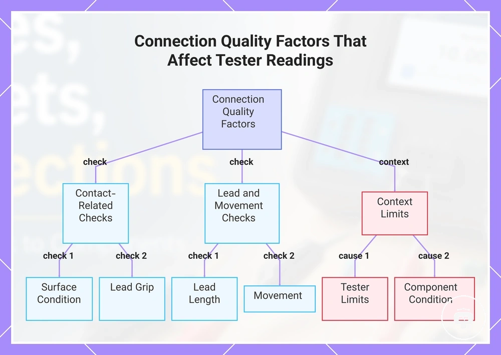
Connection quality factors that affect tester readings are often visible at the contact point. The diagnostic checklist below focuses on contact-related causes before assuming a fault with the tester or component. Check surface condition, lead grip, lead length, movement, and testing context.
- Surface condition: Check for dirty metal, oxidation, or contamination that may increase contact resistance and contribute to unreliable readings.
- Lead grip: Look for a loose grip, poor contact, or bent leads that may interrupt electrical contact during testing.
- Lead length: Long probe leads may increase movement and can influence sensitive readings under some conditions.
- Movement: Confirm that probes, clips, or sockets remain steady throughout the measurement to reduce intermittent contact.
- Context limits: If connection quality appears satisfactory but tester readings remain unstable or detection is missing, the cause may instead relate to tester limits or component condition.
When a loose grip, dirty metal, bent leads, or long probe leads are present, improving the connection may reduce contact-related symptoms. However, an unstable reading or missing detection does not necessarily mean the connection is the only cause. The issue may instead involve tester limits or component condition.
Check connection quality before drawing conclusions from unexpected tester readings because visible contact faults are often easier to identify than less obvious causes. The following subsections examine each connection factor in more detail.
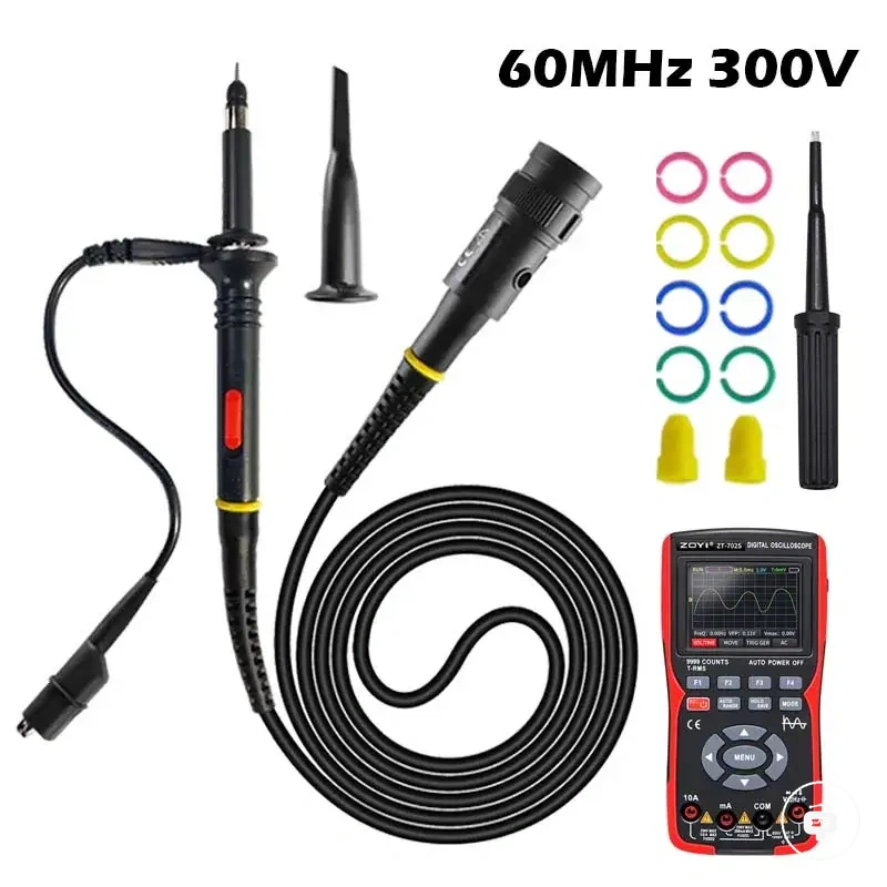
Here are product examples that may make comparison easier. Before buying, always review the compatibility criteria, essential features, and product details.
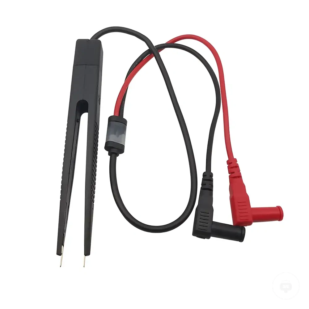
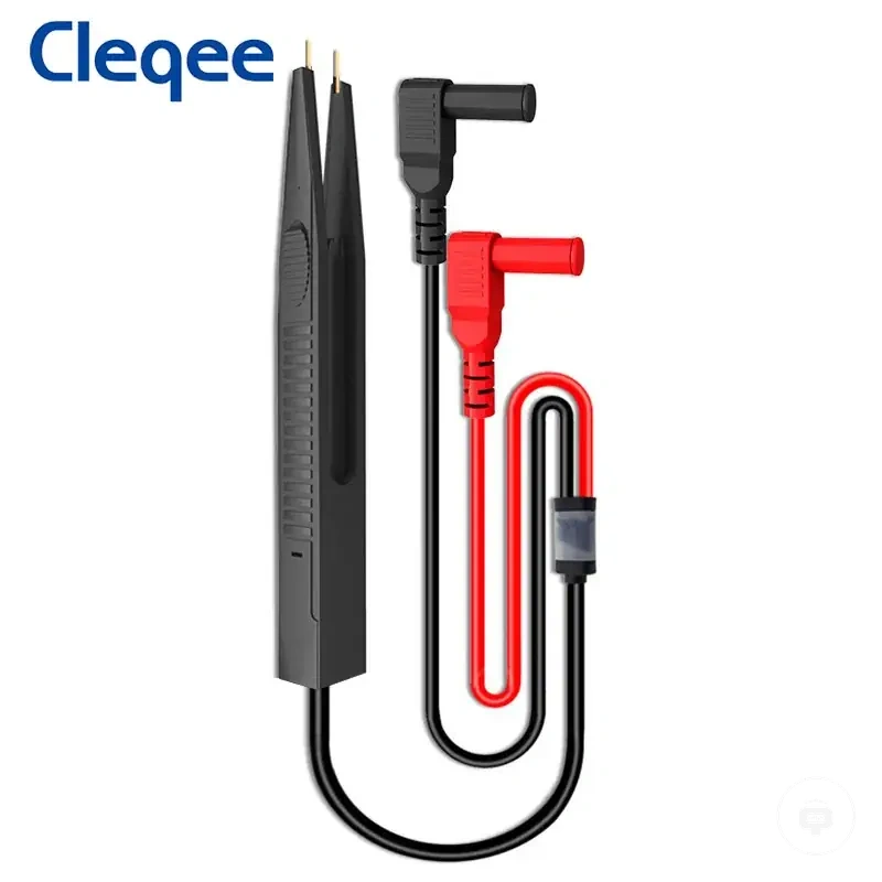
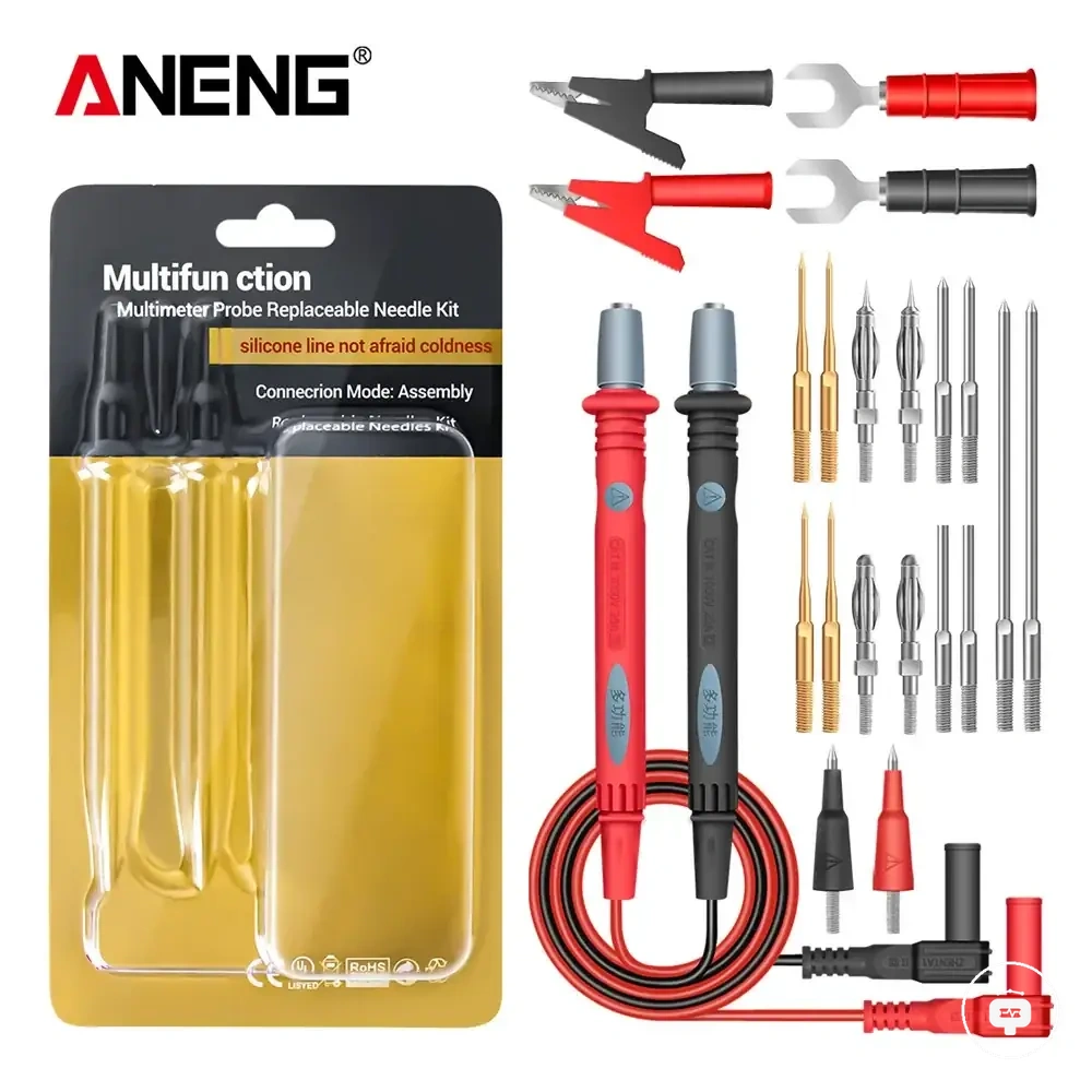
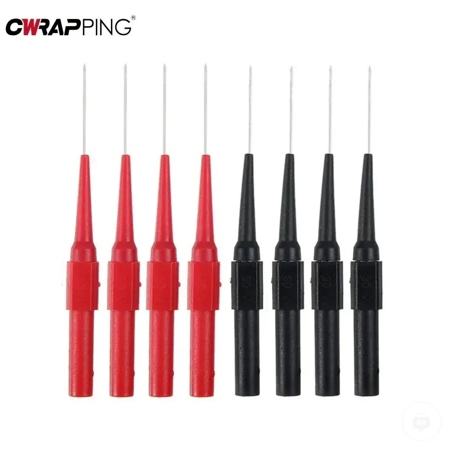
This chart shows the main connection quality factors to check when tester readings are unstable, and the context limits to consider if contact checks are satisfactory.
Contact Resistance, Oxidation, and Loose Grip
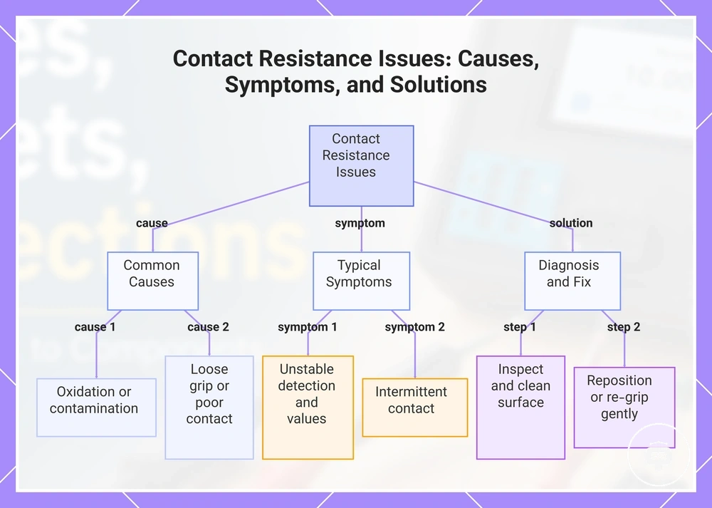
When contact resistance increases because of oxidation or a loose grip, detection and measured values may become unstable or inconsistent. Cleaning the contact surface, careful repositioning, or gentle re-gripping can help when poor contact is the local cause, although the outcome depends on the condition of the connection. Contact faults often appear as intermittent contact, unreliable detection, or changing measured values.
Start with visible and tactile checks before assuming a larger fault.
- Inspect the contact surface for oxidation, dirty contact, or contamination, and clean it carefully when appropriate for the component and connection.
- Check for a loose grip or poor contact, then try gentle repositioning or re-gripping if the connection appears unstable.
- Avoid excessive grip or scraping because small component leads can be bent or damaged, creating additional connection problems.
This chart shows the common causes of contact resistance problems, their typical symptoms, and the recommended diagnostic and repair steps.
Stray Capacitance from Long Probe Leads
Stray capacitance from long probe leads is a connection-related effect that may influence sensitive readings under some tester and component conditions. Longer probe lead length or closer lead spacing can introduce additional lead capacitance that affects small-value measurements, although the influence varies by tester model and component range. The effect is most relevant when measurements are sensitive to small changes in the connection.
When small-value measurements behave inconsistently, long probe leads may be one possible contributing factor. For example, a reading taken with long probe leads may vary more than one taken with shorter, stable, and separated leads under the same testing conditions. Shorter, stable, and separated leads are generally preferable when sensitive readings remain inconsistent, but the possible influence still depends on the tester model and component range.
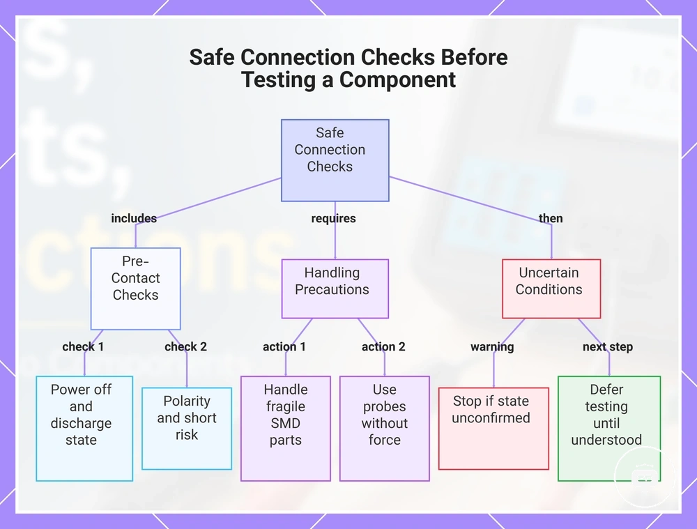
Safe Connection Checks Before Testing a Component
Safe connection checks help confirm suitable conditions before testing a component and can reduce avoidable connection risk. Verify the power state, discharge state, polarity, and short risk before making contact. These checks help protect the tester, component, and surrounding circuit without implying complete safety.
Before contact is made, confirm the required safety conditions.
- Ensure the powered circuit is switched off before connecting the tester.
- Confirm that any charged capacitor has been discharged before making contact.
- Check polarity, isolate exposed leads where practical, and position probes to reduce short risk.
- Stop if the power state, discharge state, or connection condition cannot be confirmed.
When fragile SMD parts require direct contact, handle the probe, clip, or tweezer carefully to reduce connection risk. Follow the guidance for using probes and sockets without applying unnecessary force. Controlled handling may reduce the chance of disturbing small contacts.
For uncertain in-circuit conditions, defer testing until the connection state is understood. The guidance on in-circuit and out-of-circuit testing can help determine whether to proceed or stop.
This chart shows the essential safety checks and precautions to perform before testing a component, including pre-contact checks, handling precautions, and actions for uncertain conditions.