In-Circuit vs Out-of-Circuit Testing with Electronic Component Testers
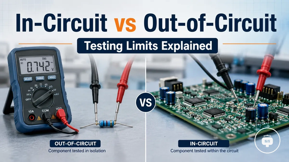
In-circuit testing and out-of-circuit testing with a component tester differ because the testing state can influence how measurements are taken and interpreted. In-circuit testing evaluates a component while it remains connected to a circuit, whereas out-of-circuit testing measures the component after it has been isolated from surrounding electrical paths.
A component tester may produce different measurement results depending on whether other circuit elements influence the test. In-circuit testing can provide a useful indication of component condition without removing the part, while out-of-circuit testing can reduce interference from connected components and may provide results that are easier to interpret. The most suitable approach depends on the tester capability, the circuit configuration, and the diagnostic objective.
How In-Circuit and Out-of-Circuit Component Testing Work
In-circuit testing and out-of-circuit testing differ because the connection state of a component influences how a component tester measures and interprets it. In-circuit testing measures a component while it remains installed in a circuit, whereas out-of-circuit testing measures the same component after it has been isolated from surrounding electrical paths.
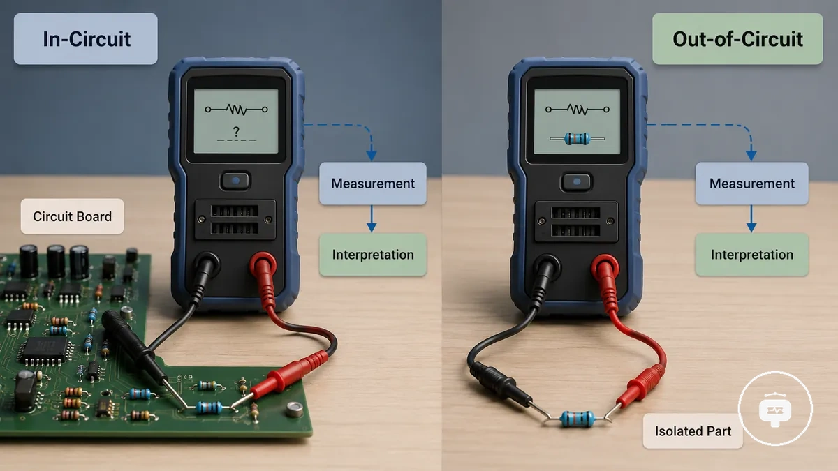
The connection state affects how the measurement is obtained and how the result should be interpreted. The available component testing capability may also depend on the testing method, the component being evaluated, and the influence of the surrounding circuit on the measurement.
Understanding the comparison becomes easier when the testing conditions are viewed side by side.
| Testing method | Connection condition | Measurement influence | Interpretation impact |
|---|---|---|---|
| In-circuit testing | Component remains connected to the circuit. | Surrounding electrical paths may influence the measured values. | Results can support an initial assessment but may require interpretation within the circuit context. |
| Out-of-circuit testing | Component is isolated before measurement. | The measurement is taken with less influence from other connected components. | Results may be easier to interpret because the component is measured more directly. |
In-Circuit Testing for Components on Circuit Boards
A component tester can evaluate an installed component while it remains connected to a circuit board. Because the component is still electrically connected to surrounding circuitry, the measurement reflects both the installed component and its interaction with the circuit, so the diagnostic value depends on the circuit design and the tester capability.
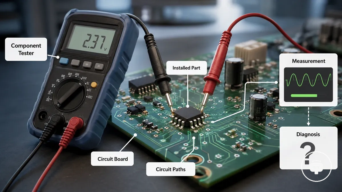
A common use case is checking an assembled circuit board to determine whether a component may need further investigation before it is removed. In this situation, the component tester can provide useful diagnostic information without immediately isolating the component. Following guidance on how to use the tester can help ensure the tester is applied appropriately during in-circuit measurements.
- The installed component remains connected to other electrical paths on the circuit board.
- Measurement interactions may be influenced by surrounding components and circuit connections.
- The interpretation of measured values depends on both the installed component and the connected circuit.
- In-circuit testing can support preliminary diagnosis, but the outcome varies with the circuit configuration and the capabilities of the component tester.
Out-of-Circuit Testing for Isolated Electronic Components
Out-of-circuit testing begins by isolating the component so a component tester can measure it through a direct connection. Because the isolated component is no longer influenced by surrounding circuit paths, the measured values may be easier to interpret, although the diagnostic outcome still depends on the component's condition and the capabilities of the tester.
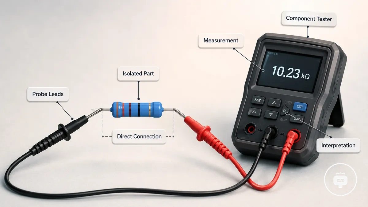
An isolated component is commonly connected to the tester using probe leads or a socket instead of remaining attached to the circuit board. Using an appropriate probe and socket setup can help establish a direct measurement connection while recognising that isolation alone does not guarantee a definitive diagnosis.
For example, removing a component that requires closer evaluation may improve confidence in the measurement because surrounding circuit influence is reduced. Even then, the measured values should be interpreted according to the condition of the isolated component and the purpose of the test.
Before performing an isolated measurement, consider these conditions:
- Confirm that the component is fully isolated from connected circuit paths.
- Use direct contact with suitable probe leads or a compatible socket.
- Interpret measured values in the context of both the isolated component and the tester capability.
- Isolation can reduce circuit influence, but measurement interpretation still depends on testing conditions and component state.
Accuracy and Limitations of Component Testers in Circuit Testing
The accuracy of a component tester depends on the measurement conditions under which the test is performed. Circuit influence, component condition, and tester capability can all affect the measured values, so the reliability of the result should be evaluated within the testing environment rather than treated as an absolute indication of component condition.
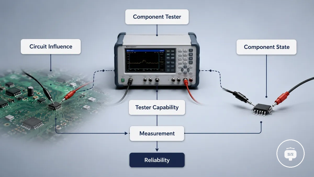
The factors below show why measurement results can differ between testing conditions. For broader discussion of accuracy and limitations and the different roles of measurement tools, see tester versus multimeter limits.
| Measurement condition | Influencing factor | Effect on reliability |
|---|---|---|
| Component connected to a circuit | Electrical interaction with surrounding components and circuit paths | Measured values may be influenced by the complete circuit, requiring careful interpretation. |
| Component tested in isolation | Direct connection between the component tester and the component | Reduced circuit influence may improve confidence in interpreting the measurement. |
| Different testing situations | Component state and tester capability | Measurement reliability depends on the testing conditions and should be qualified accordingly. |
Why Component Testers May Not Detect Components In Circuit
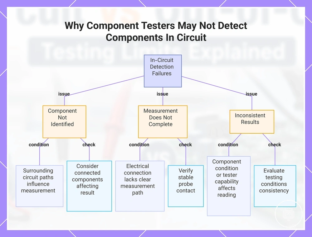
When a component tester does not detect or measure a component while it remains connected to a circuit, circuit conditions are often influencing the measurement. Detection depends on the interaction between the installed component, the surrounding electrical paths, and the capabilities of the tester, so an undetected component should not be treated as evidence of a single fault.
The following diagnostic checks can help identify conditions that may prevent reliable detection. For broader troubleshooting related to not detecting parts, compare the observed symptom with the testing conditions before drawing conclusions.
- Detection issue: The component is not identified. Contributing condition: Surrounding circuit paths may influence the measurement. Symptom: No usable identification is displayed. Check: Consider whether connected components could be affecting the result.
- Detection issue: The measurement does not complete. Contributing condition: The electrical connection may not provide a clear measurement path. Symptom: The tester cannot produce a result. Check: Verify that the probes are making stable contact with the component.
- Detection issue: The result appears inconsistent. Contributing condition: Component condition or tester capability may influence the reading. Symptom: Measurements vary between attempts. Check: Evaluate whether the testing conditions remain consistent.
- Detection issue: Repeated in-circuit testing does not provide a reliable reading. Contributing condition: The installed circuit configuration may limit detection. Symptom: The component cannot be evaluated with confidence. Check: When appropriate, isolating the component or using another measurement approach may provide additional diagnostic information.
This chart shows the main detection issues, their contributing conditions, and recommended checks for in-circuit component testing.
Choosing the Right Testing Method for Component Diagnosis
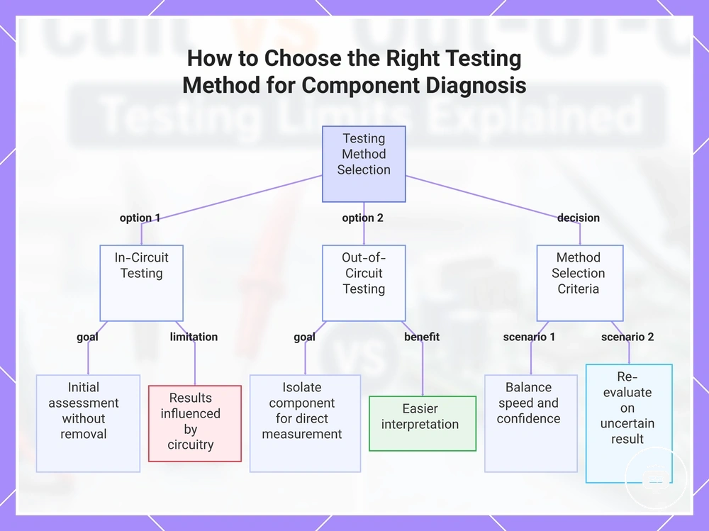
Choosing the appropriate testing method depends on the diagnostic goal, the circuit condition, and the level of measurement confidence required. In-circuit testing may suit an initial assessment when access and speed matter, while out-of-circuit testing may better match situations where isolation and clearer interpretation are more important.
Use the criteria below to match the testing goal with the circuit condition and the confidence needed from the measurement.
- Testing goal: Perform an initial assessment without removing the component. Circuit condition: The component remains installed. Measurement confidence: Results may be influenced by surrounding circuitry. Suitable method: In-circuit testing may be appropriate.
- Testing goal: Reduce the influence of connected circuit paths. Circuit condition: The component can be isolated. Measurement confidence: Direct measurement may be easier to interpret. Suitable method: Out-of-circuit testing may be appropriate.
- Testing goal: Balance access and speed with diagnostic confidence. Circuit condition: Component access and removal effort vary. Measurement confidence: The preferred method depends on whether rapid screening or isolated evaluation is the priority. Suitable method: Choose the method that matches the diagnostic objective.
- Testing goal: Investigate an uncertain or inconsistent result. Circuit condition: The initial measurement does not provide a clear conclusion. Measurement confidence: A different testing condition may improve interpretation. Suitable method: Consider another testing approach when the first method does not provide sufficient confidence.
This chart shows the two main testing methods and the criteria for selecting between them based on diagnostic goal, circuit condition, and measurement confidence.