
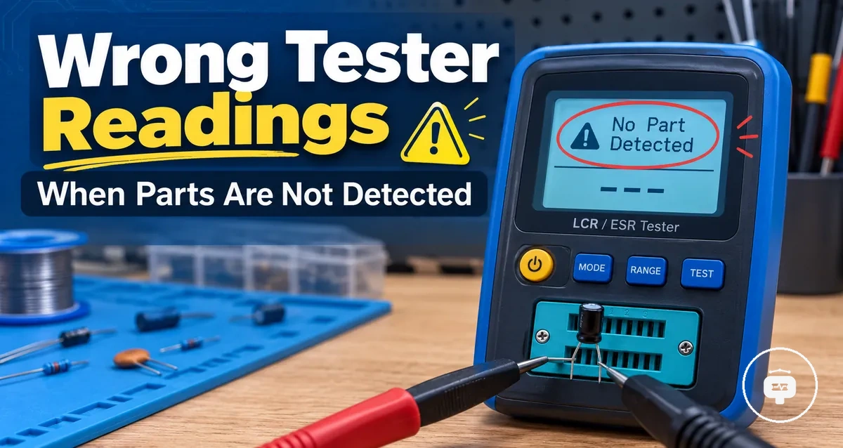
Electronic Component Tester Wrong Readings and Detection Failures
When a component tester produces wrong readings or fails to detect a part, the result may reflect a measurement error, an unstable connection, the component condition, or the testing setup. An unknown result does not by itself confirm that the component is defective.
The component tester may measure or identify a part differently when socket contact, probe placement, component leads, or test conditions change. Incorrect values and detection failures therefore require diagnosis across the tester, the connection points, and the component rather than one assumed cause.
This troubleshooting scope covers unexpected readings, failed recognition, connection factors, and testing conditions. Each symptom should be evaluated in context before repair, calibration, or replacement is considered.
Why Electronic Component Testers Give Incorrect Readings or Show Unknown Results
Component tester results depend on the component state, connection quality, and tester condition. Incorrect readings or unknown results can appear when one or more of these conditions affect how the tester measures or identifies a component, so the displayed result should be interpreted within the testing context rather than treated as a final diagnosis.
A broad evaluation is usually more reliable than assuming a single fault. Measurement capability, connection stability, and testing conditions can all influence the outcome, and understanding accuracy limits helps explain why different situations may produce different readings. An unknown result does not always mean that the tested component has failed.
- Component state may affect identification or measured values.
- Probe or socket connections can influence measurement stability.
- Tester condition or operating state may affect detection behaviour.
- Testing conditions can change how the component tester interprets the connected part.
The image below shows the relationship between the tester, the connected component, and the connection points that may influence measurement results. It illustrates the conditions being evaluated rather than a confirmed fault.
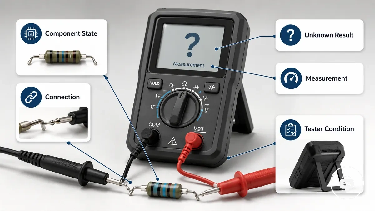
Viewing these conditions as connected diagnostic factors creates a clearer basis for interpreting specific symptoms without assuming that every unexpected reading has the same cause.
Common Symptoms of Electronic Component Tester Problems
Symptoms show how a component tester behaves during measurement, but they do not by themselves identify the underlying cause. False readings, an unknown component result, and inconsistent measurements can each indicate a testing condition that requires further evaluation.
Symptoms should be recognised before they are interpreted. The same visible result may appear with different components or testing setups, so a single symptom should not be treated as proof of a specific failure.
The checklist below groups common user-observed symptoms without assigning a definite cause or recommending a repair method.
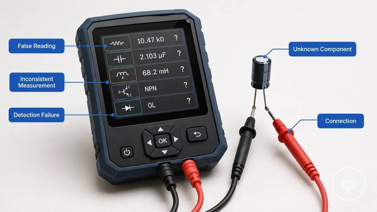
- Incorrect values: The displayed measurement differs from the expected result and may indicate a condition that requires further checking.
- Unknown component: The tester displays an unknown result or cannot identify the connected part, which does not necessarily mean the component has failed.
- Inconsistent measurement: Repeated tests show different values or different identifications under similar conditions.
- Detection failure: The tester does not recognise the connected component or displays no meaningful result.
- Unstable display: Readings change unexpectedly during repeated measurements, indicating that further diagnosis may be needed.
Wrong Values, False Readings, and Inconsistent Measurements
When a measured value differs from the expected component attribute, the result may indicate a measurement-related symptom rather than a confirmed fault. A resistance, capacitance, or other measured value can vary when the testing conditions, component state, or measurement setup differ from what was expected.
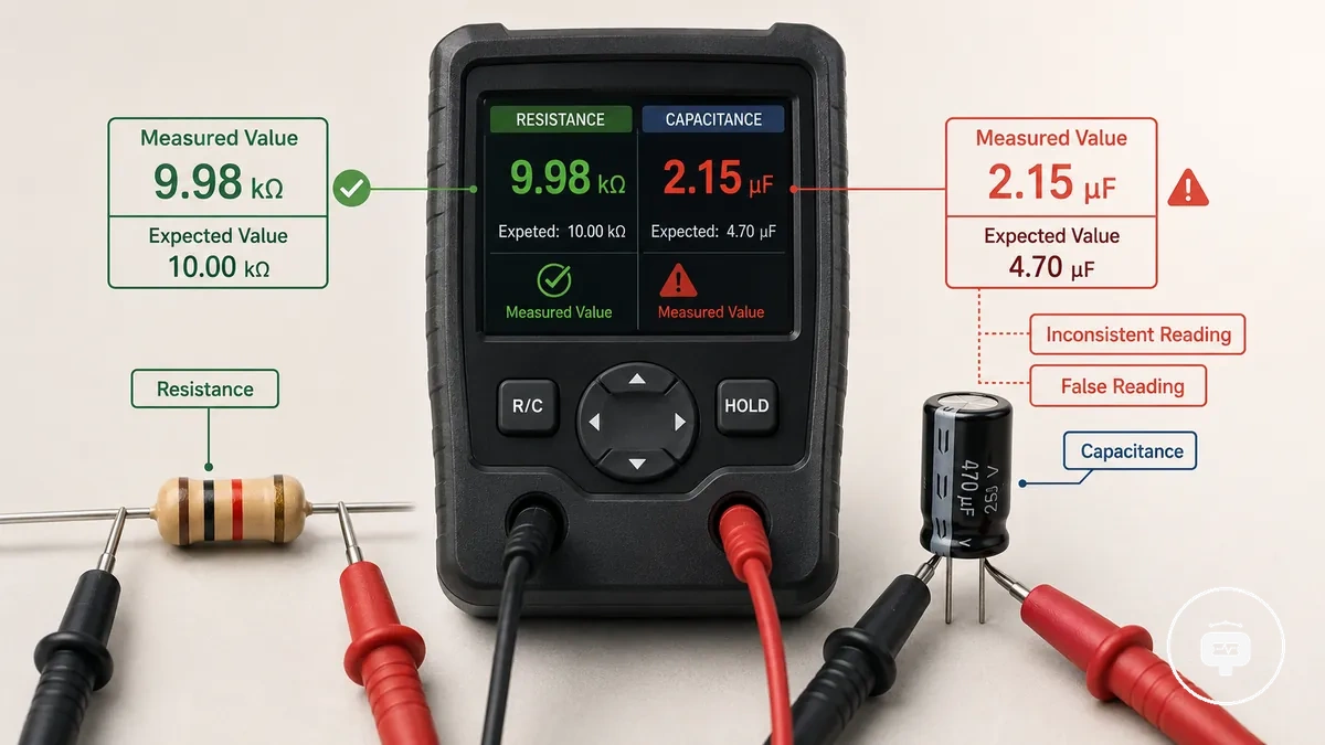
Measurement results should be compared with the expected component attribute while recognising that repeated tests may not produce identical readings. An inconsistent reading may suggest that an influencing condition is affecting the measurement, but the symptom alone does not identify a single cause.
- Resistance mismatch: The measured resistance differs from the expected value and may reflect the testing condition or component state.
- Capacitance mismatch: The displayed capacitance does not match the expected attribute under the current measurement conditions.
- False reading: The measured value appears unreasonable or unexpected for the component being tested.
- Inconsistent reading: Repeated measurements of the same component produce different values under similar testing conditions.
Unknown Components and Failed Detection Results
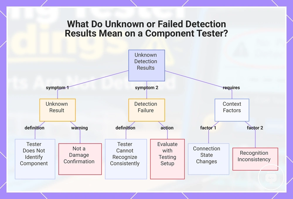
When a component tester displays an unknown result or fails to detect a connected part, the tester has not recognised the component under the current testing conditions. An unknown result is a diagnostic symptom and does not by itself confirm that the component is damaged.
The tester recognition process may depend on the component type, connection state, and measurement conditions. A detection failure can occur when the tester cannot identify the connected part consistently, so the result should be evaluated together with the testing setup rather than treated as a definite diagnosis.
The checklist below separates common recognition-related states without assigning a single cause:
- Unknown result: The tester does not identify the connected component and displays an unknown state.
- Detection failure: The tester does not recognise the component during the measurement process.
- Connection state: The recognition result may change when the component connection or contact condition changes.
- Component recognition: A recognised component on one test and an unknown result on another may indicate that further evaluation is needed rather than confirming a defective component.
This chart breaks down the meaning of unknown and failed detection results, separating symptoms from interpretation factors.
Causes Behind Component Tester Detection and Measurement Errors
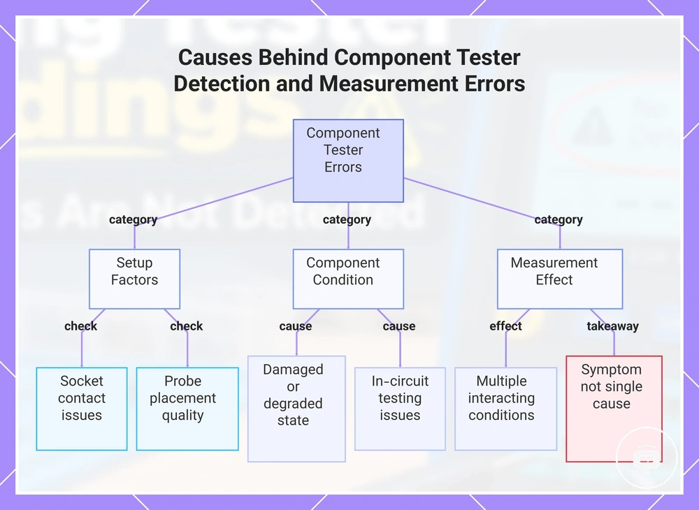
When an electronic component tester produces incorrect readings or fails to recognise a component, multiple conditions may interact to affect the result. The testing setup, connection quality, component condition, and measurement environment can each influence detection or measured values, so symptoms should be interpreted by evaluating the complete testing situation rather than assuming a single cause.
Setup-related factors are often the first conditions to examine because the socket, probe placement, and connection quality can influence measurement behaviour. Following a proper testing workflow may help reduce setup-related inconsistencies, although results can still vary with the connected component and testing conditions.
Component condition is another category that can affect tester recognition and measured values. A damaged, degraded, or unstable component state may influence how the tester identifies or measures the part, while in-circuit testing issues can change the measurement environment and affect recognition behaviour without indicating a single underlying cause.
The checklist below groups common cause categories that may contribute to incorrect detection or measurement results:
- Socket: Poor contact or unstable insertion may influence component recognition and measurement consistency.
- Probe: Probe placement or contact quality can affect the measured result.
- Setup: Testing conditions may create measurement effects that differ from the expected component attribute.
- Component condition: The physical or electrical state of the component may affect how the tester detects or identifies it.
- Measurement effect: Multiple influencing conditions can interact, so the observed symptom may not indicate a single underlying cause.
This chart shows the main cause categories that can lead to incorrect readings or failed component recognition, helping to interpret symptoms by evaluating the complete testing situation.
Socket, Probe, and Connection Problems Affecting Test Results
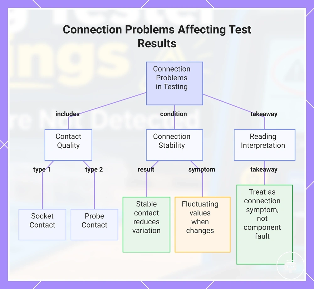
Connection method can influence measurement reliability when socket contact, probe contact, or connection stability changes during testing. An unstable electrical contact may affect how the tester measures or recognises a component, so unexpected readings should be interpreted as possible connection-related symptoms rather than confirmed component faults.
Socket contact and probe contact should remain stable throughout the measurement process because changes in physical contact can influence the reading effect. The same component may produce different results when the connection state changes, even if other testing conditions remain similar.
The checklist below highlights common connection conditions that may influence measurement reliability:
- Socket contact: Incomplete or unstable contact may affect component recognition or measured values.
- Probe contact: Probe placement and contact quality can influence measurement consistency.
- Stable connection: Consistent electrical contact may help reduce variation between repeated measurements.
- Reading effect: Fluctuating or unexpected values may occur when connection conditions change during testing.
This chart shows the key connection conditions that influence measurement reliability and how to interpret unexpected readings.
Component Condition and Testing Setup Factors That Change Results
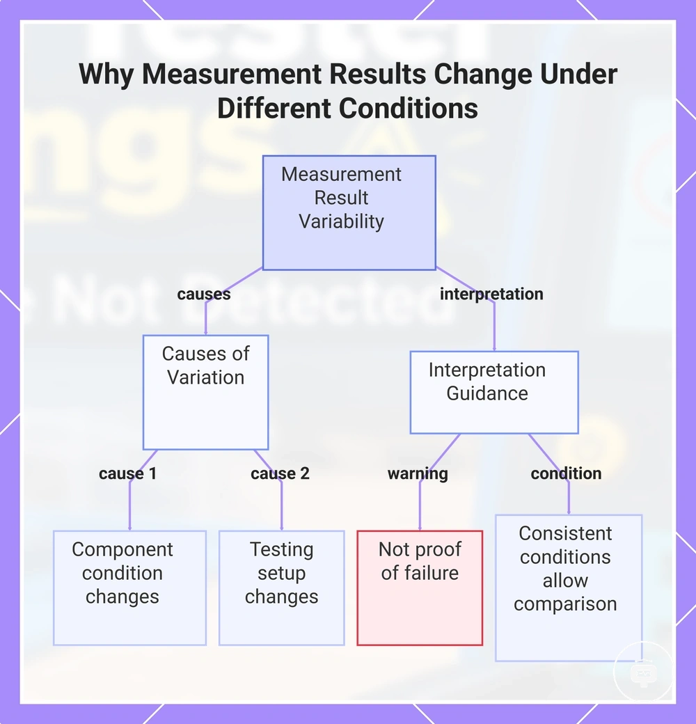
When the component condition or testing setup changes, the observed measurement may also change even when the same tester is used. Component state, setup conditions, and the test environment can each influence the displayed result, so an unexpected reading should not be treated as proof that the component has failed.
A stable component in one test environment may produce a different result under changed setup conditions. For example, a change in component state or test setup can affect the measurement outcome, so users should read results correctly before drawing conclusions from the displayed values.
Result interpretation depends on the relationship between component condition and testing setup. When conditions remain consistent, repeated measurements may be more comparable, while changes in the setup or component state can produce different measurement effects that require conditional interpretation.
This chart explains the main causes of measurement variation and provides guidance on how to interpret results without falsely concluding component failure.
Fixing Electronic Component Tester Wrong Readings
Fixing incorrect readings starts with verifying the testing conditions before assuming that the tester or component is faulty. The appropriate correction depends on the observed symptom, so each check should confirm whether the reading changes under consistent test conditions before moving to the next step.
Use the following checklist to verify common conditions and apply practical corrections. If repeated checks still produce inconsistent results, it may be appropriate to calibrate the tester before drawing conclusions about measurement accuracy.
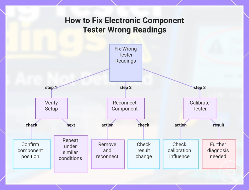
- Verify the setup: Confirm that the component is positioned correctly, then repeat the measurement under similar testing conditions.
- Reconnect the component: Remove and reconnect the component, then repeat the test to determine whether the displayed result changes.
- Repeat the measurement: Compare repeated readings. If the result remains consistent, interpretation may be more reliable. If the values continue to vary, continue checking the setup and tester condition.
- Perform a calibration check: If measurement differences remain after verifying the setup and repeating the test, check whether calibration may be influencing the observed result.
Correction depends on the identified cause. When a verification step changes the displayed result, the issue may relate to the testing conditions. If the same symptom remains after these checks, further diagnosis may be needed rather than assuming that the tester or component has failed.
This chart shows the step-by-step troubleshooting process to correct wrong readings from an electronic component tester, including setup verification, reconnection, and calibration checks.
Checking Connections and Repeating Tests Correctly
When an electronic component tester produces an unreliable reading, immediate verification should focus on the connection state, component placement, and repeat measurement conditions. Repeating the test under consistent conditions may help determine whether the displayed result changes before further diagnosis is considered.
- Verify the connection: Check that the component remains securely connected, as changes in contact may influence the measurement.
- Confirm component placement: Verify that the component is positioned consistently before repeating the measurement.
- Repeat the measurement: Perform another measurement using the same setup and compare the displayed result with the previous reading.
- Verify repeated results: If repeated measurements remain similar, the reading may be more consistent. If the result changes, verify the connection state and component placement again before continuing.
When Calibration Checks or Tester Hardware Inspection Are Needed
Further tester inspection becomes appropriate when incorrect readings continue after basic verification checks produce consistent but unreliable results. The decision to inspect the tester or perform a calibration check depends on the observed symptoms and the tester condition rather than every measurement problem requiring the same response.
If repeated verification does not change the outcome, additional evaluation may be appropriate. When measurement accuracy remains uncertain after basic checks, users may need to calibrate the tester as part of a broader verification process instead of assuming that calibration is always required.
The following checklist can help determine whether further inspection is appropriate:
- Basic verification: Confirm that repeated measurements under similar conditions continue to produce the same unexpected result.
- Calibration indicator: Consider a calibration check when repeated verification does not explain the measurement behaviour.
- Self-test: If the tester includes a self-test function, verify its result before assuming a hardware issue.
- Hardware condition: Inspect the tester for visible wear or damage that may affect measurement reliability.