How to Read Electronic Component Tester Results
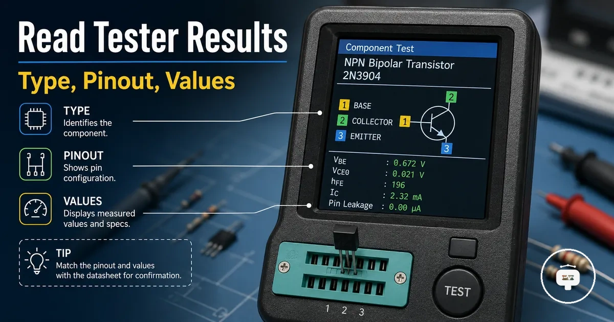
Electronic component tester results are the displayed identities, values, and conditions produced after a component is detected and measured. The display can present component identification, measured values, and pin information, while the exact measurement output may vary with the tester model and the condition of the connected component.
Interpreting the tester screen involves reading each displayed field as part of a complete result rather than relying on a single value. Component type, displayed values, pin information, and other measurement output together provide the context needed to understand what the electronic component tester has identified.
The interpretation process begins with understanding the overall display before examining individual fields and values. This macro view creates the foundation for reading the display accurately as the following sections explain each result in more detail.
Understanding Electronic Component Tester Display Results
A display result is the component-detection output shown on the tester screen, where the detected component type is presented together with supported measurements. Each measurement field represents a specific part of the displayed information, such as identification, measured values, or pin information. The layout and available fields may vary depending on the electronic component tester. Reading the complete display result provides the context needed before interpreting individual values.
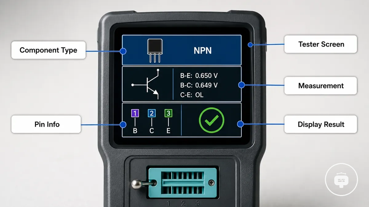
Screen labels identify the meaning of each measurement field instead of acting as separate results. The detected component type establishes what the tester has identified, while the remaining fields provide related measurement output for that detection. Interpreting these display fields together helps maintain the relationship between component identification and the information presented on the tester screen without assuming that every tester uses the same display format.
Component Identification and Pinout Information
Component identification shows the detected component type together with the pinout information that the tester can determine. The result may also indicate terminals and polarity when those attributes are supported by the tester's capabilities and can be identified from the connected component. Reading these detected attributes together provides a more reliable basis for interpreting the identification result.
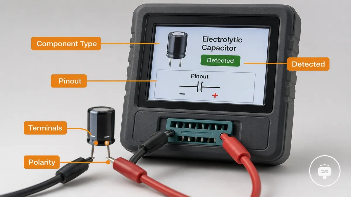
The identification result can include the following elements:
- Component type – the detected device category.
- Pinout – the relationship between detected terminals.
- Terminals – the pin positions shown by the tester.
- Polarity – orientation information when the tester is able to determine it.
After identifying these attributes, it is helpful to use the tester correctly so that the displayed information can be interpreted consistently. Reading the detected component type together with the pinout and polarity provides practical context for understanding the remaining display fields.
Measurement Values and Labels Shown on Tester Displays
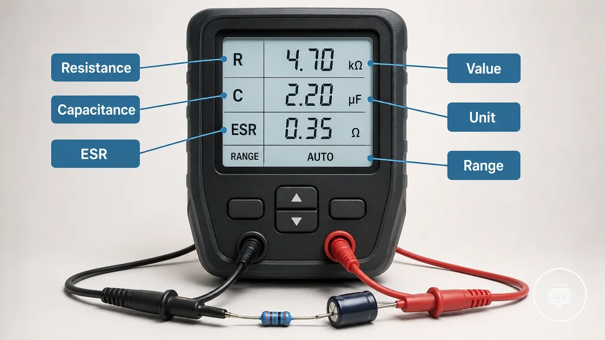
Measurement labels identify what each displayed value represents, while the corresponding value shows the result for that measurement field. Labels such as resistance, capacitance, and ESR indicate the type of measurement rather than its quality or accuracy. Each value label should be interpreted together with its measurement range because the available measurements and displayed fields may vary by tester model.
| Label | Measurement | Meaning | Interpretation Condition |
|---|---|---|---|
| Resistance | Resistance value | Represents electrical resistance | Interpret within the displayed measurement range |
| Capacitance | Capacitance value | Represents electrical capacitance | Depends on the tester's available measurement functions |
| ESR | Equivalent series resistance | Represents the displayed ESR reading | Shown only when supported by the tester |
A common misunderstanding is expecting identical value labels to produce identical readings on every tester. Reading reliability depends on tester capability and operating conditions, so understanding accuracy limitations provides useful context when interpreting results. Measurement labels represent the type of reading, while the displayed values should be interpreted within the tester's supported measurement range and capabilities.
Reading Component-Specific Tester Measurements
After a component has been detected, the measured value should be interpreted according to the identified component type. A measured value for a resistor, capacitor, or transistor represents different electrical characteristics, so its meaning depends on the detected component and the tester's available measurement capabilities.
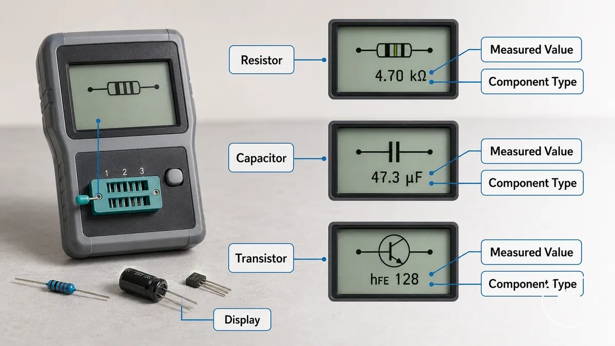
Common component measurement interpretations include:
- Resistor – the measured value represents the displayed resistance reading.
- Capacitor – the measured value may represent capacitance and, on supported testers, may also include related measurements such as ESR.
- Transistor – the measured value is interpreted together with the detected transistor information and the characteristics shown on the display.
A measured value should always be interpreted within the context of the detected component because different component categories use different measurement meanings. The displayed results may vary with tester capability and the condition of the connected component, so interpreting the measured value together with the detected component provides the most meaningful understanding of the displayed measurement without assuming identical results across all testers.
Capacitance and ESR Values in Capacitor Results
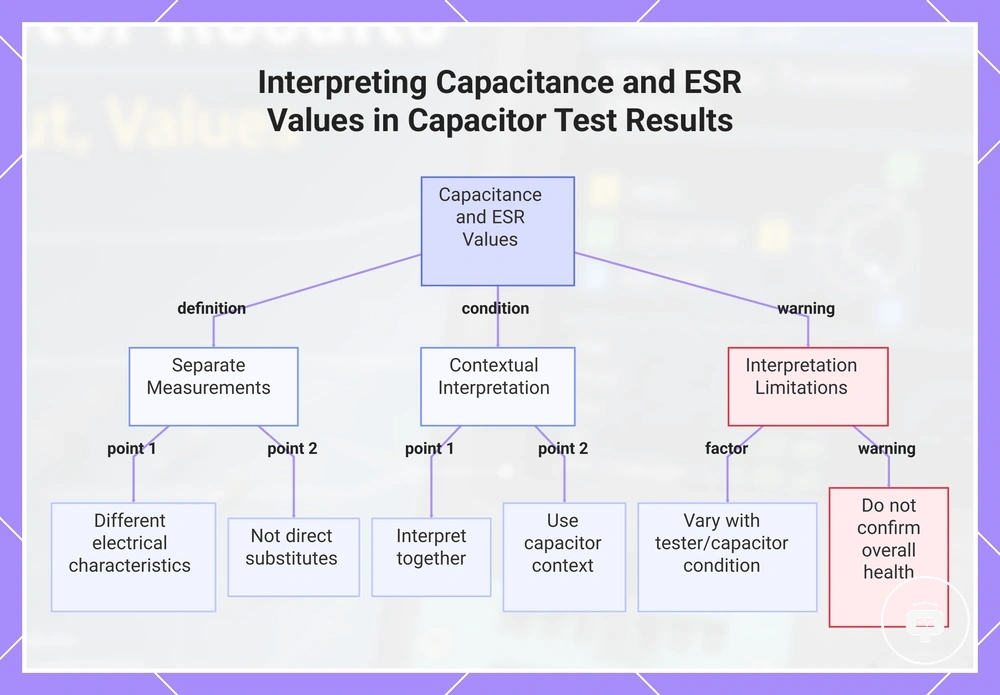
Capacitor readings may include both a capacitance value and, on supported testers, an ESR value. The capacitance value represents the measured capacitance, while the ESR value represents equivalent series resistance. Because these values describe different electrical characteristics, they should be interpreted as separate measurements rather than as direct substitutes for one another.
Capacitor capacitance and ESR values are most useful when interpreted together and in the context of the detected capacitor. The displayed values may vary with the tester's capabilities and the condition of the connected capacitor, so they can provide measurement information without confirming the overall condition or health of the capacitor by themselves.
This chart explains how to interpret capacitance and ESR values from capacitor test results, including their separate meanings, contextual use, and limitations.
Transistor and Semiconductor Identification Results
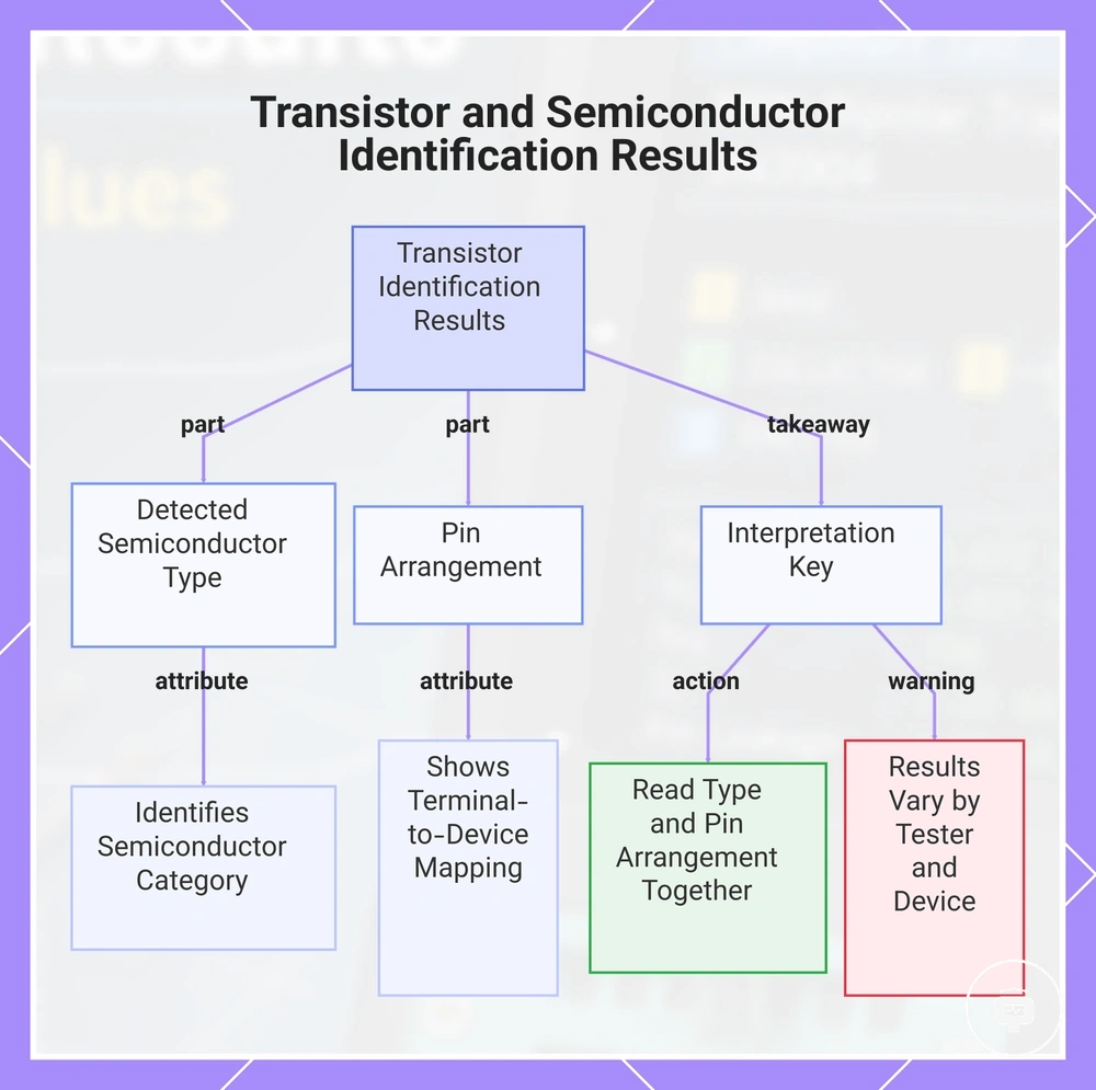
A transistor result may show the detected semiconductor type together with its pin arrangement. The detected type identifies the semiconductor category recognised by the tester, while the pin arrangement indicates how the displayed terminals relate to that detected device. The available result fields may vary with the tester and the connected semiconductor.
Transistor results should be interpreted by reading the detected type and pin arrangement together. The detected semiconductor type provides the identification context, while the displayed pin arrangement clarifies that specific result without implying that every semiconductor can be identified under all conditions.
This chart shows the two main components of a transistor identification result and how to interpret them correctly.
Interpreting Unknown Component Detection Results
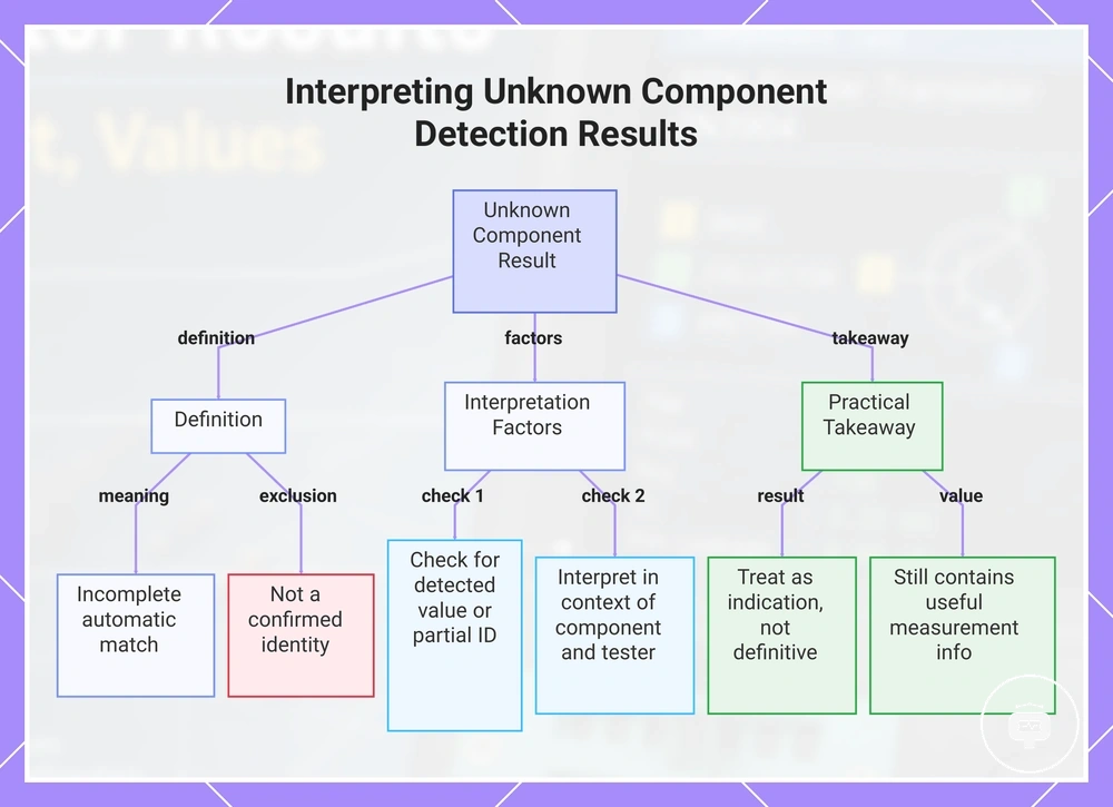
An unknown component result indicates that automatic identification may not have produced a complete or confident match. The tester may still show a detected value or partial identification fields, but the result should be treated as incomplete rather than as a confirmed component identity. When reviewing the result, consider these interpretation factors:
- Check whether a detected value appears with the unknown component result.
- Identify whether automatic identification produced a partial detected type or no identification.
- Interpret displayed values within the available result context rather than assuming complete identification.
- Consider that the result may depend on the connected component and the tester's identification capabilities.
An unknown component result can still indicate useful measurement information even when identification is incomplete. If automatic identification remains uncertain, treat the displayed result as an indication rather than a definitive identity because the outcome may vary with the component and the available measurement information.
This chart explains the definition, key interpretation factors, and practical takeaway for unknown component detection results.
Conditions That Affect Electronic Component Tester Readings
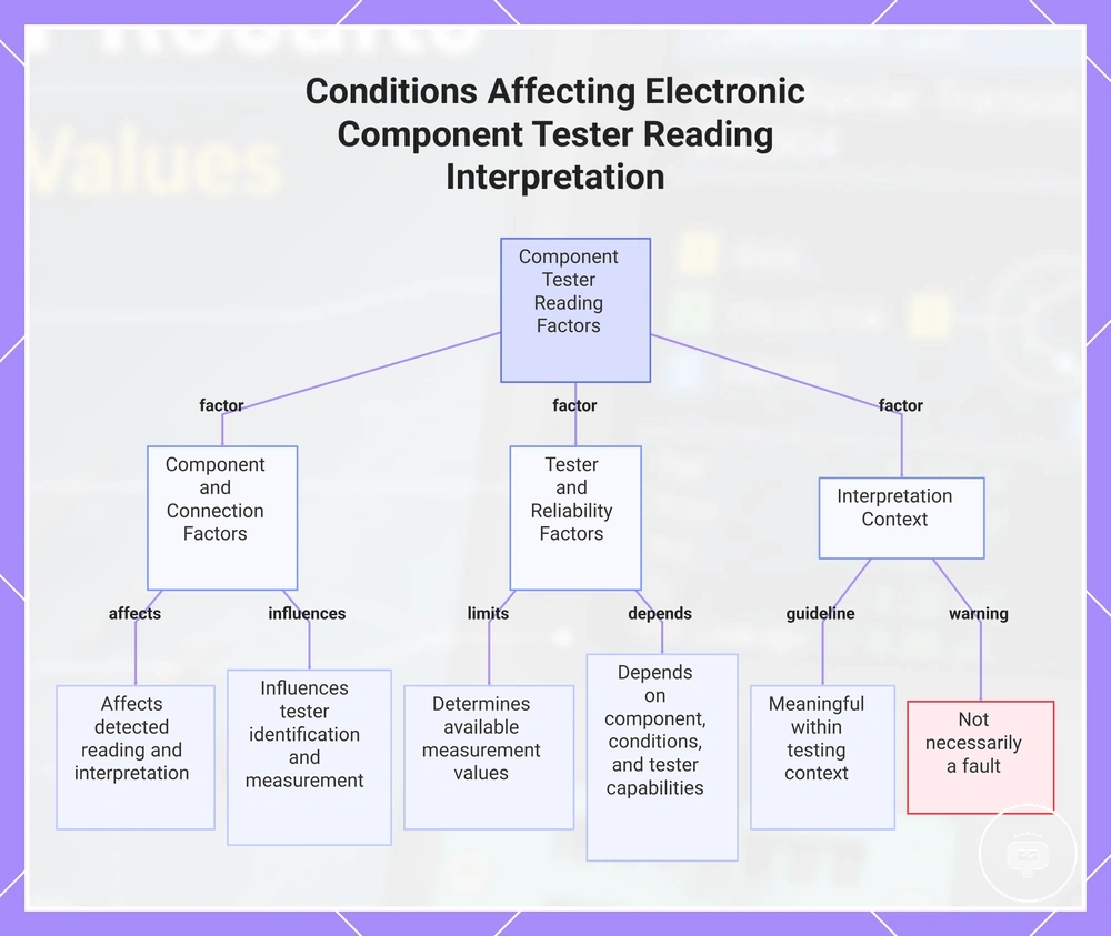
Reading interpretation depends on factors such as component condition, connection method, tester limitation, and reading reliability. These conditions can affect how a result should be interpreted, so the displayed measurement is most meaningful when considered within its testing context rather than as an isolated value.
When assessing a reading, consider the following factors:
- Component condition may affect the detected reading and its interpretation.
- Connection method can influence how the tester identifies and measures the connected component.
- Tester limitations may determine which measurement values or identification fields are available.
- Reading reliability depends on the connected component, the testing conditions, and the tester's capabilities.
These conditions affect interpretation but do not necessarily indicate a fault. If the focus is diagnosing unexpected or inconsistent readings rather than understanding interpretation factors, see wrong result causes for troubleshooting-specific guidance.
This chart shows the key factors that influence how electronic component tester readings are interpreted, including test setup, tester and reliability factors, and the interpretation context.