
Electronic Component Tester Accuracy and Practical Measurement Limits
Electronic component tester accuracy refers to how closely an electronic component tester can estimate a component's characteristics under its intended test conditions. These tools provide practical support for component identification and repeatable bench checks rather than laboratory-grade certainty. Their accuracy is practical and context-dependent.
Measurement confidence depends on factors such as component type, measurement range, tolerance, contact quality, calibration state, and whether further verification is required. Reading confidence may also vary with the condition of the component and the consistency of the test setup. Stable readings can improve confidence in repeatability, but they should not be treated as guaranteed correctness.
In practical use, an electronic component tester can provide sufficient accuracy for identifying components and comparing repeatable measurements, while precision measurement may require additional verification when decisions depend on tighter tolerances. This distinction helps separate practical limitations from unrealistic expectations of measurement reliability. For broader buying and selection context, see the electronic component tester guide.
| Practical use | Precision limit |
|---|---|
| Supports component identification, repeatable bench checks, and decision confidence based on consistent displayed values. | Verification may still be needed when calibration, tolerance, or measurement requirements demand greater confidence than a practical component tester can provide. |
What Accuracy Means for Electronic Component Testers
Electronic component tester accuracy is the relationship between the displayed value and the component's expected or true value under the tester's measurement conditions. Accuracy defines how closely the tester output represents the component being measured, but it does not prove that the displayed value is exact. The displayed value is an estimate within the limits of the tester, the component condition, and the measurement conditions.
What accuracy means depends on comparing the tester reading with the expected component value rather than viewing the displayed value in isolation. The annotated example below highlights the displayed value, the expected or reference value, and the role of tolerance in interpreting the measurement.
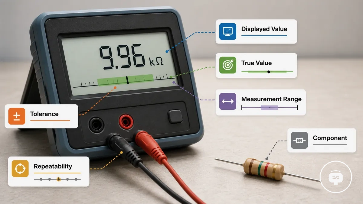
The relationship between the displayed value, the true value, tolerance, and the applicable measurement range determines how the reading should be interpreted. Repeatability can increase identification confidence when similar measurements remain consistent, although a stable reading may still differ from the true value. A useful tester reading is not the same as a calibrated reference measurement, yet a tester can still provide practical value for component identification and routine bench work when used within its intended purpose.
Accuracy, Precision, and Repeatability
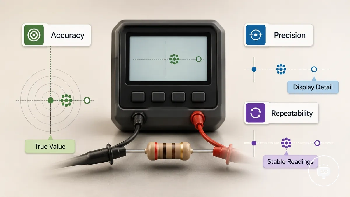
Accuracy describes how closely a reading matches the true value, precision describes the level of display detail, and repeatability describes the consistency of repeated readings. Although these terms are closely related, they represent different measurement qualities. Stable readings should not be mistaken for automatically correct readings.
Accuracy, Precision, and Repeatability are often confused when interpreting component tester displays. The diagram below separates the three concepts by showing the difference between correct readings, detailed readings, and consistent readings.
| Term | What it means | What it does not prove |
|---|---|---|
| Accuracy | Closeness of the displayed value to the true value or reference value. | That every reading is correct under every condition. |
| Precision | Display detail and the ability to distinguish small differences between readings. | That a detailed reading is close to the true value. |
| Repeatability | Consistency across repeated readings under similar conditions. | That stable readings are automatically accurate. |
Imagine a component measured multiple times with nearly identical results. Those repeated readings demonstrate repeatability, but they may still remain offset from the reference value. This simple scenario shows that consistency alone does not necessarily indicate accuracy.
Ballpark Identification Versus Exact Measurement
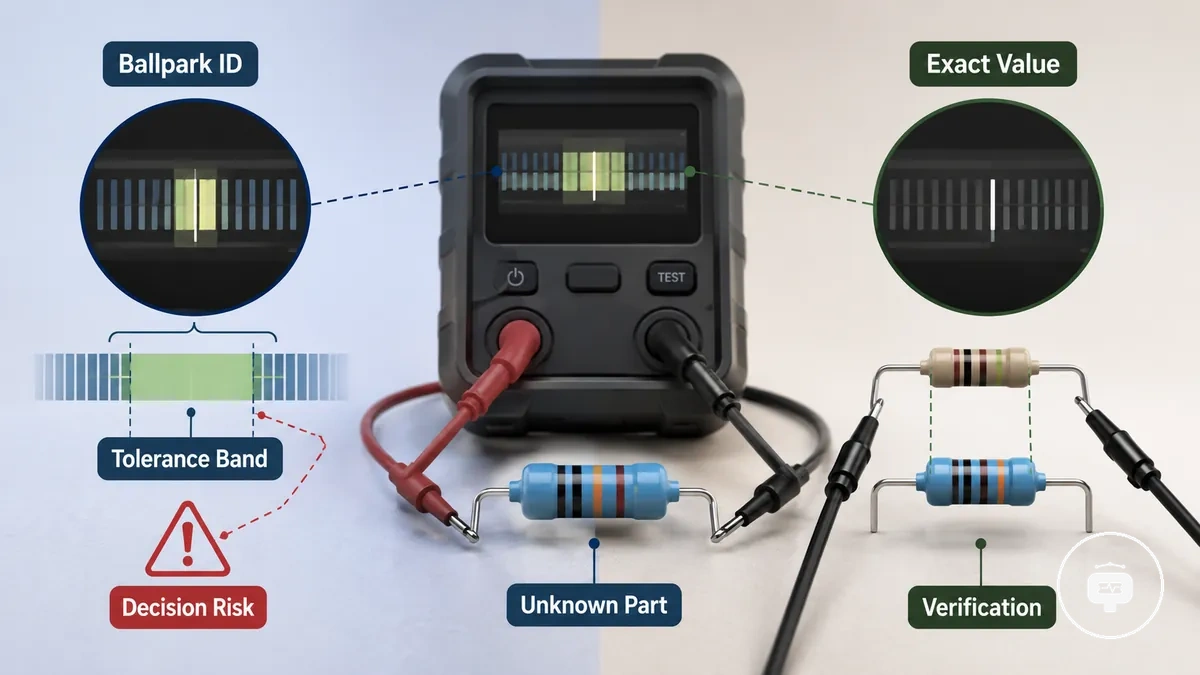
Ballpark identification and exact measurement serve different purposes when evaluating electronic components. A component tester can help identify loose components and unknown parts by estimating a component value, making ballpark identification practical for many tasks, but it is not always sufficient.
Ballpark Identification Versus Exact Measurement compares two different uses of tester readings. The comparison below and the accompanying graphic show when an approximate identification may be adequate and when verification of an exact value becomes more appropriate.
| Ballpark identification | Exact measurement |
|---|---|
| Suitable for identifying unknown parts, estimating a component value, sorting loose components, and supporting repair triage when a tolerance band allows an approximate result. | Suitable when verification of the component value is needed because tighter tolerance requirements or higher decision risk make an exact measurement more important. |
Imagine identifying an unknown component removed from a circuit board before deciding whether it can be reused. An approximate reading may provide enough confidence to continue repair triage, while a confirmation measurement may be preferred if the component value affects a critical decision. The need for exact measurement depends on the tolerance band and the decision risk associated with the result.
Measurement Conditions That Affect Reading Reliability
Measurement conditions affect reading reliability because the displayed value depends on the relationship between the component, the test setup, and the tester rather than on the tester alone. The same component may produce different displayed values when testing conditions change, even if the tester itself remains unchanged. Reading reliability is therefore conditional.
When two plausible readings differ, the cause may lie in the testing conditions instead of the component. Component type, measurement range, contact quality, socket fit, and probe stability can all influence reading confidence, while battery level and tester state may also affect how consistently the tester detects and reports a displayed value. These condition groups organize the main factors that qualify reading reliability without indicating that any single condition proves correctness or fault.
Measurement Conditions That Affect Reading Reliability become easier to interpret when the major condition groups are viewed together. The annotated illustration below organizes the relationship between contact, range, power state, and component behavior, while the table summarizes how each condition group may influence reading confidence.
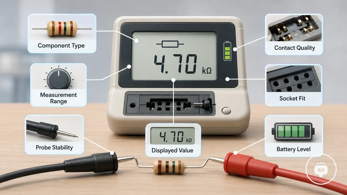
| Condition | Affected attribute | Typical reading effect | What to check |
|---|---|---|---|
| Component type and measurement range | Displayed value and reading confidence | Readings may vary when the component characteristics or measurement range differ. | Confirm the component type and use an appropriate measurement range. |
| Contact quality, socket fit, and probe stability | Connection quality | Inconsistent contact may reduce reading confidence or produce unstable readings. | Check lead contact, socket fit, and probe stability. |
| Battery level and tester state | Power state and repeatability | Reading consistency may vary when tester power or operating state changes. | Check battery level and verify that the tester is operating normally. |
Component Type and Measurement Range
Component type and measurement range affect whether a tester can produce a reliable value because different component categories behave differently within the tester's supported measurement range. Resistors, capacitors, inductors, diodes, and transistors may produce more dependable readings when the measured value remains within a suitable range position. Reading confidence therefore depends on the relationship between component type and measurement range.
When a displayed value appears uncertain, the component may be near a low-value edge, outside the supported range, or affected by out-of-range behavior rather than by a fault in the tester. ESR-like readings, low-value components, and semiconductor identification can all require careful interpretation because reading confidence may vary with the component category and range position. The table below summarizes common component families, their range concerns, and the associated reading risks. If you need broader coverage of supported testing capability, see measurement ranges.
| Component family | Range concern | Reading risk |
|---|---|---|
| Resistors and capacitors | Low-value edge or supported range limits | Displayed values may become less reliable near range boundaries. |
| Inductors | Measurement range suitability | Reading confidence may vary with range position. |
| Diodes and transistors | Identification and value interpretation | Identification may remain useful even when exact value interpretation requires additional verification. |
| ESR-like readings | Range suitability and out-of-range behavior | Results may require cautious interpretation when measurement conditions reduce reading confidence. |
Lead Contact, Socket Fit, and Probe Stability
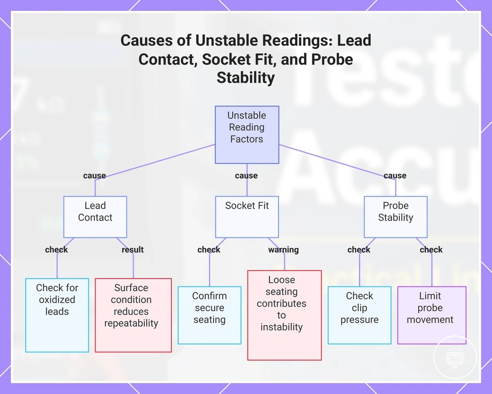
When readings become unstable, lead contact, socket fit, and probe stability may be contributing factors even if the component and tester are otherwise suitable. Changes in physical connection can affect the displayed value and repeatability, so contact quality is a common reason for unstable readings.
Physical connection quality depends on the condition of the leads, socket, and probes rather than on a single factor. Oxidized leads, a loose ZIF socket, reduced clip pressure, probe movement, excessive lead length, or inconsistent repeated seating may influence reading stability. These conditions do not necessarily indicate a faulty component, but they can qualify how confidently a displayed value should be interpreted. A brief contact and seating check can help determine whether unstable readings are related to the physical connection.
- Check lead contact for oxidized leads, as surface condition may reduce contact quality and affect repeatability.
- Check socket fit by confirming the component is seated securely in the ZIF socket, since loose seating may contribute to unstable readings.
- Check clip pressure, because inconsistent pressure may change probe contact and the displayed value.
- Limit probe movement during measurement, as changing contact may reduce reading stability.
- Check lead length, since longer leads may introduce additional variation under some test conditions.
- Use repeated seating to see whether a more consistent connection improves reading stability.
This chart shows the three main physical connection factors that can cause unstable readings and the key checks for each.
Battery Level, Power Stability, and Tester State
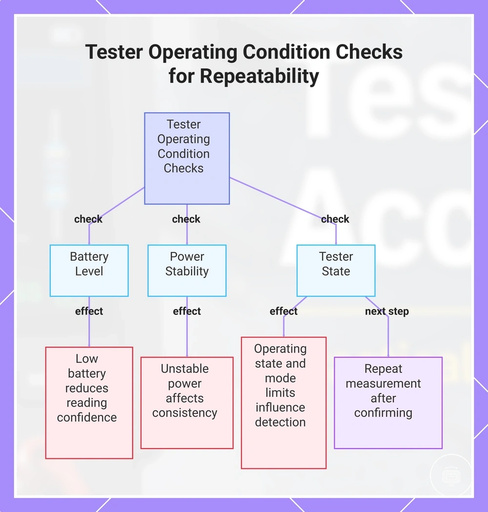
Battery level, power stability, and tester state can influence repeatability and detection behavior because the tester's operating condition may affect how consistently it produces a displayed value. A low battery, unstable power, or a changed tester state may reduce reading confidence under some conditions, and the effect can vary by model.
When repeated readings become inconsistent, checking the tester's operating state can help determine whether the variation is related to the tester rather than the component. The checklist below verifies common operating-state conditions that may influence repeatability without implying that every tester behaves the same way. These checks help qualify reading confidence rather than replace calibration or model-specific guidance. After confirming the tester condition, repeat the same measurement to compare repeatability under similar operating conditions.
- Check the battery level, as a low battery may reduce reading confidence on some testers.
- Confirm power stability, because unstable power may affect the consistency of the displayed value.
- Verify the tester state after a recent reset or during a self-test state, since the operating state may influence detection behavior.
- Review any mode limits or operating mode changes, and allow normal warm-up behavior where relevant, because these conditions may qualify reading interpretation.
- If readings remain uncertain, repeat the same measurement after confirming the tester condition to compare repeatability.
This chart shows the key checks for tester operating conditions that influence reading repeatability and the recommended next step after verification.
Practical Limits Behind Wrong or Unstable Values
Wrong values and unstable readings usually relate to range limits, circuit influence, poor contact, component condition, or detection limits rather than one definite fault. Non-detection and unexpected auto-identification can also occur when the tester cannot interpret the component or test conditions with enough confidence. These causes should be grouped before the reading is used for a decision.
When a displayed value shifts, appears implausible, or fails to appear, the same symptom can have more than one likely cause. A range issue may reduce confidence in the value, circuit influence may alter what the tester detects, poor contact may create unstable readings, and component condition may affect detection. The table below maps each symptom to a likely attribute issue, a local check, and the resulting decision risk without treating the symptom as proof of failure.
| Symptom | Likely attribute issue | Check | What it means |
|---|---|---|---|
| Wrong or unexpected value | Range limits, circuit influence, or component condition | Compare the test conditions with the expected component type and range. | The reading may have limited confidence and may need verification before a higher-risk decision. |
| Unstable readings | Poor contact, changing test conditions, or circuit influence | Check contact consistency and repeat the measurement under similar conditions. | Variation may reflect the setup rather than a component fault. |
| Non-detection | Detection limits, unsupported behavior, or component condition | Confirm the component is connected correctly and within the tester's practical detection capability. | Non-detection does not by itself identify the component as faulty. |
| Incorrect auto-identification | Ambiguous component behavior, circuit influence, or detection limits | Repeat the test under similar conditions and compare the result with the expected component category. | The displayed label may have lower identification confidence and should not be treated as a final conclusion. |
These symptoms should be interpreted as confidence signals rather than absolute fault conclusions. When the result affects a repair or replacement decision, use wrong readings troubleshooting for a fuller diagnostic process.
Range Edges and Low-Value Measurements
Range edges and low-value measurements deserve extra caution because readings near the low end, high end, or resolution boundary may be more sensitive to tester limitations. Low resistance, small capacitance, and ESR-like values can be influenced by lead resistance, resolution limits, and display rounding. These edge-of-range values are caution zones rather than automatically valid or invalid results.
Range-edge behavior means that small changes in test conditions or display resolution may have a larger effect on how the value is interpreted. The table below groups common low-value and range-boundary conditions by their likely source of sensitivity and the confidence that may be placed in the result. Readings used for sensitive decisions should be repeated or verified when the possible error could affect the outcome.
| Measurement condition | Why it is sensitive | What to do with the reading |
|---|---|---|
| Low resistance | Lead resistance and contact effects may become significant relative to the measured value. | Treat the result as conditional and compare repeated readings under similar contact conditions. |
| Small capacitance | Resolution limits and display rounding may reduce value confidence near the lower range boundary. | Use the reading as an estimate unless the decision requires separate verification. |
| ESR-like values | Low-value measurements may be sensitive to connection quality, range position, and tester interpretation. | Repeat the measurement and avoid treating one displayed value as conclusive. |
| High-end or edge-of-range values | The reading may approach the tester's practical detection or display limits. | Use added caution and verify the result when decision risk is high. |
In-Circuit Influence on Measured Values
In-circuit influence can affect measured values because a circuit-connected component may share electrical paths with surrounding parts. Parallel paths, charged capacitors, semiconductors, board contamination, and partial discharge can all influence how the tester interprets the component. As a result, surrounding circuit paths may affect the displayed value even when the component itself has not changed.
Imagine measuring the same component first as a loose component and then while it remains circuit-connected. The contrast below shows how surrounding circuit conditions may qualify the reading without implying that every in-circuit result is unreliable.
| Loose component reading | Circuit-connected reading |
|---|---|
| The tester measures the component with fewer influences from surrounding circuit paths, making value interpretation more direct. | Parallel paths and semiconductors in the circuit may influence the displayed value or component identification. |
| Board contamination and stored charge are less likely to influence the reading once the component is appropriately isolated. | Charged capacitors, partial discharge, or board contamination may contribute to shifting or unexpected measured values. |
Whether circuit influence affects the reading depends on the circuit layout and component connections. Isolation may be appropriate when surrounding circuit paths prevent a confident interpretation or when a measurement must represent the loose component rather than the connected circuit effect.
Auto-Detection Limits and Component Identification Errors
When auto-detection mislabels parts or fails to detect a component, the signal pattern is often too ambiguous for reliable component identification. A displayed component label may therefore have reduced identification confidence without indicating that the tester is defective. Auto-detection depends on interpretable component behavior.
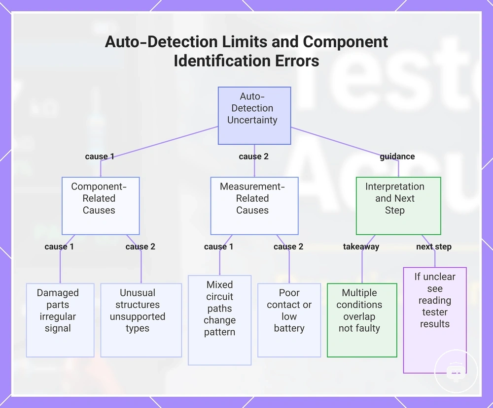
Automatic detection compares measured electrical behavior with expected signal patterns, but more than one condition can influence the result. The following cause-and-effect relationships explain why detection uncertainty may occur without implying tester failure.
- Damaged parts may produce an irregular signal pattern, which can reduce identification confidence or cause the tester to mislabel parts.
- Unusual semiconductor structures or unsupported component types may not match the tester's expected detection patterns, increasing identification ambiguity.
- Mixed circuit paths may change the measured signal pattern, which can affect the displayed component identification.
- Poor contact or a low battery may reduce signal quality, causing auto-detection to fail to detect a component or lower identification confidence.
- Multiple conditions may overlap, so a detection error does not necessarily indicate a faulty component or a defective tester.
If the displayed type, pinout, or measured value remains unclear after repeated measurements, see reading tester results for additional guidance on interpreting the displayed information.
This chart shows the main causes of auto-detection uncertainty and how to interpret detection errors without assuming tester failure.
Realistic Accuracy Expectations for Low-Cost Testers
Low-cost testers can provide practical value when their realistic accuracy is evaluated against the intended measurement task rather than the price alone. Confidence may depend on factors such as component range, display resolution, contact hardware, stated tolerance, build quality, and available calibration support. A lower price level should not be treated as automatic inaccuracy.
Imagine using a budget tester to identify loose components and perform repeatable repair checks before deciding whether additional verification is needed. In many hobby and repair situations, usable identification and consistent readings may provide acceptable confidence when the tester is used within its practical limits. When tighter stated tolerance requirements or higher measurement risk are involved, build quality, calibration support, and contact hardware may become more significant. The appropriate level of confidence depends on the intended use case rather than cost alone.
Comparing the main cost-related factors helps set balanced expectations instead of assuming that all affordable testers perform alike. The table below summarizes common cost-value trade-offs and highlights when each factor may influence confidence, while keeping the final decision focused on measurement needs rather than purchase price.
| Cost-related factor | Accuracy implication | When it matters |
|---|---|---|
| Display resolution | Greater display detail may improve reading interpretation but does not by itself increase measurement accuracy. | When distinguishing small differences between displayed values. |
| Contact hardware | Connection quality may influence repeatable repair checks and reading confidence. | When measuring small leads or repeating the same test. |
| Stated tolerance | Stated tolerance helps qualify expected confidence in the measurement. | When measurement decisions depend on closer value agreement. |
| Calibration support | Calibration support may improve long-term measurement confidence, depending on the tester. | When consistent measurements are required over time. |
| Price level | Price savings may increase measurement risk if important features or support are limited. | When higher-confidence measurement decisions are required. |
Evaluate the complete cost-value trade-off against the intended application, because measurement confidence should be based on suitability rather than price alone.
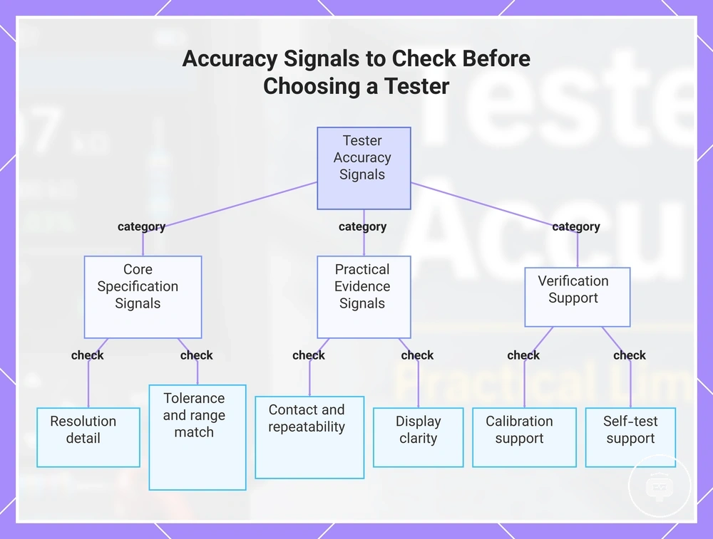
Accuracy Signals to Check Before Choosing a Tester
Accuracy signals should be evaluated as practical decision criteria when choosing a tester. The most useful signals show how the tester may perform within the required component range and measurement conditions. These accuracy-related features should guide the buying decision more than cosmetic specifications.
Resolution, stated tolerance, and supported range are core specification signals because they qualify how much detail the tester displays and where that detail may remain useful. Higher resolution can improve reading detail, but it does not by itself confirm accuracy. A stated tolerance can help frame expected confidence, while the supported range should match the component values likely to be tested. Range coverage and tolerance should therefore be considered together rather than treated as isolated claims.
Stable contacts, repeatability, and display clarity provide practical evidence of how easily readings can be obtained and interpreted. Contact hardware should hold component leads consistently, repeated tests should produce reasonably similar results under similar conditions, and the display should separate component identification from the measured value clearly. These signals are usually more relevant to measurement confidence than decorative screens, extra colours, or other weakly related features.
Calibration support and self-test support may add confidence when they help verify that the tester is operating as expected. Check whether the design provides understandable status signals, reference-check behaviour, or access to appropriate calibration checks without assuming that the presence of a self-test proves correctness. These features should qualify the selection decision rather than replace range, tolerance, contact, and repeatability criteria.
The checklist below organizes the main criteria by what to look for and why each signal may affect measurement confidence. Use the accuracy signals together as a selection framework, because no single feature determines suitability for every testing need.
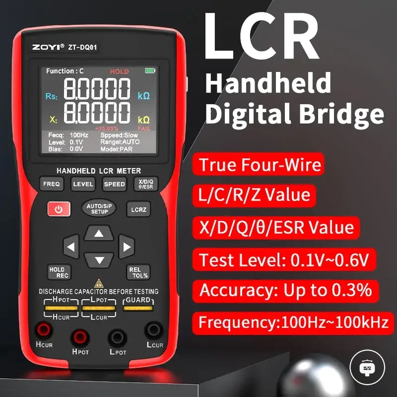
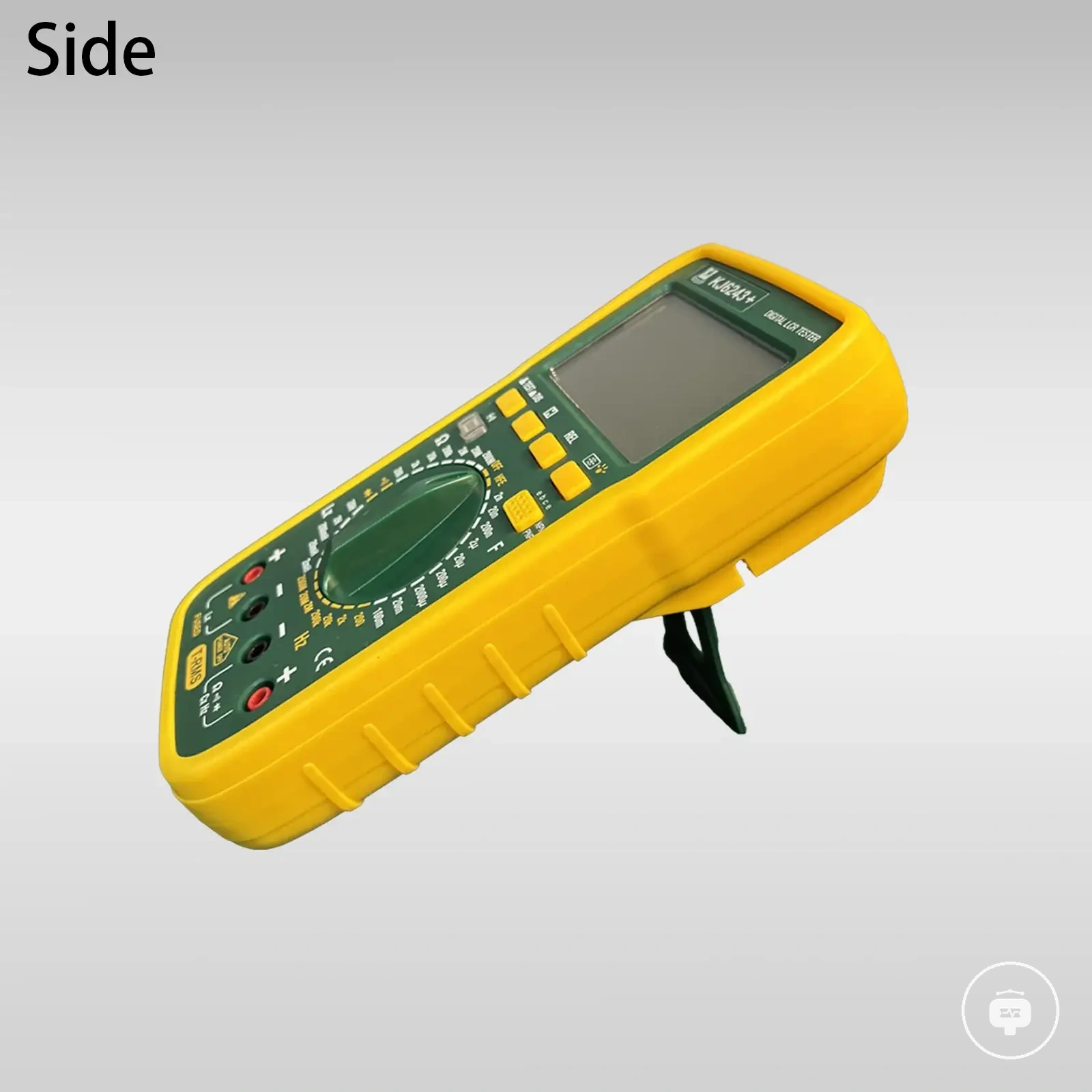
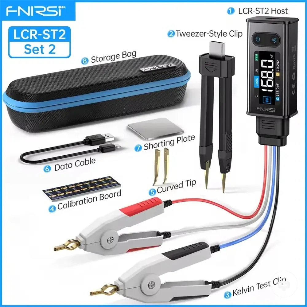
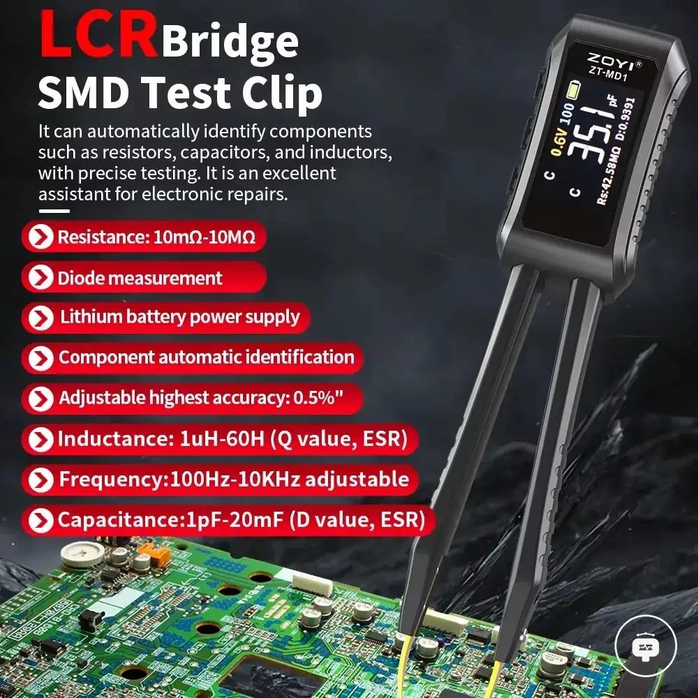
Here are product examples that may make comparison easier. Before buying, always review the compatibility criteria, essential features, and product details.

- Resolution: Check whether the displayed detail is appropriate for the value differences you need to distinguish; extra digits alone do not confirm accuracy.
- Stated tolerance: Look for a clearly presented tolerance or accuracy statement that helps qualify expected reading confidence.
- Supported range: Confirm that the relevant component types and likely values fall within the tester's stated operating range.
- Calibration support: Check whether the tester provides a practical way to verify or maintain measurement confidence over time.
- Self-test support: Look for clear operating-state or self-test information that may help identify tester-state uncertainty.
- Stable contacts: Evaluate the socket, clips, or probe contact for consistent seating because unstable contact may reduce repeatability.
- Repeatability: Consider whether repeated measurements under similar conditions are likely to remain consistent enough for the intended decision.
- Display clarity: Check that component identification, pin information, and measured values are easy to distinguish without relying on decorative presentation.
This chart organizes the main accuracy signals to evaluate when selecting a tester, grouped by core specifications, practical evidence, and verification support.
Resolution, Tolerance, and Stated Measurement Range
Resolution defines the display detail a tester can present, while tolerance and stated measurement range qualify how much confidence may be placed in the displayed value. Displayed digits can show smaller value changes, but rounding and range limits still influence interpretation. Display detail should therefore be distinguished from reliable accuracy when evaluating accuracy claims.
The table below separates display detail from trustworthy measurement range so that resolution, tolerance, and stated measurement range can be evaluated together. Tolerance language helps qualify expected confidence under stated conditions, while component-specific ranges indicate where measurements are intended to be interpreted. Displayed digits alone do not prove accuracy, and range-edge caution becomes more important when readings approach the limits of the stated range. Reading these criteria together provides a stronger basis for a buying decision than relying on any single specification.
| Criterion | What it tells you | What it does not prove |
|---|---|---|
| Resolution | How much display detail is shown through the displayed digits. | That the displayed value is accurate or unaffected by rounding. |
| Tolerance | How tolerance language qualifies expected measurement confidence. | That one tolerance applies equally across all measurements. |
| Stated measurement range | Which component-specific ranges the tester is intended to measure. | That readings near every range edge provide the same level of confidence. |
Calibration Support and Self-Test Availability
Calibration support and self-test availability should be evaluated as confidence-related criteria rather than proof of measurement accuracy. A self-test function can help indicate that the tester is operating as intended, while calibration support may improve confidence in future measurements. Calibration support therefore improves confidence but does not guarantee precision.
The checklist below separates calibration-related signals from calibration procedures so they can be assessed as buying criteria. Features may vary by model, and each signal should be considered alongside other specification criteria rather than on its own.
- Self-test mode: A self-test mode may confirm basic operating status, but it does not prove measurement accuracy.
- Shorting leads: When supported, shorting leads may assist lead resistance compensation or a reference check, depending on the tester design.
- Reference components: Reference components may help compare measurement consistency over time, but they do not verify every reading.
- Calibration prompts: Calibration prompts can indicate when attention or a calibration feature may be appropriate, without confirming exact results.
- Repeat checks: Repeat checks under similar conditions may improve confidence in reading consistency, although consistent readings alone do not confirm absolute accuracy.
If procedure detail is needed rather than selection guidance, see calibration checks.
Stable Readings Across Repeated Tests
Stable readings across repeated tests are a useful accuracy signal because they indicate how consistently a tester measures the same component under similar conditions. Repeated tests help qualify repeatability, but reading stability supports confidence rather than proving absolute accuracy.
Stable readings are most meaningful when repeat-test conditions remain comparable. The checklist below shows the local conditions that can influence repeatability and should be checked together rather than in isolation.
- Same component: Repeat measurements on the same component so changes in the reading are not caused by switching parts.
- Socket position: Keep the same socket position where practical, because a different position may change the contact condition.
- Reseated leads: Reseat the leads consistently when repeating a test, since different seating may affect reading stability.
- Battery state: Compare readings under a similar battery state, as power conditions may influence repeatability on some testers.
- Contact pressure: Keep contact pressure consistent because changing pressure may alter the electrical connection.
- Value drift: Watch for value drift across repeated tests, as shifting readings may indicate changing test conditions or reduced confidence.
When a Component Tester Is Accurate Enough
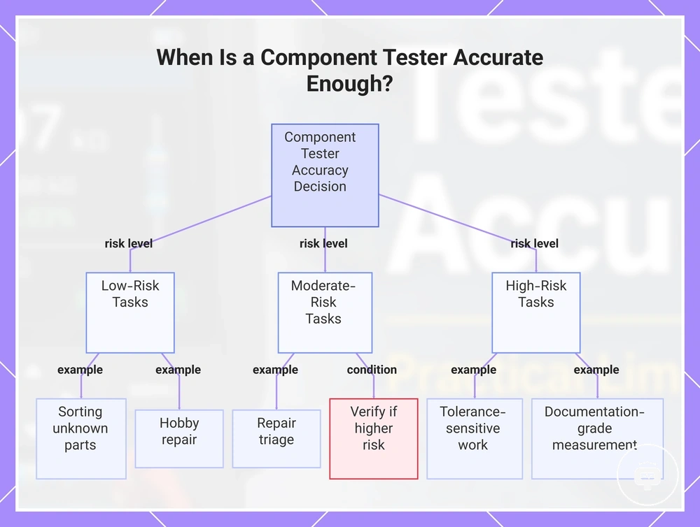
A component tester is accurate enough when its range, repeatability, tolerance expectation, and decision risk match the practical job. The required confidence depends on the measurement task rather than a universal accuracy threshold, so the tester should be evaluated against the intended use before relying on the result.
For low-risk tasks such as sorting unknown parts, stable approximate values may provide sufficient practical confidence when the tester produces consistent results within the expected range. Repeatability often matters more than fine measurement precision in these situations. For many low-risk decisions, approximate confidence may be acceptable.
For repair triage, a component tester may be accurate enough to help identify a likely failed component when repeated measurements remain consistent. The suitability of the result depends on the expected tolerance expectation and the consequences of an incorrect decision. As decision risk increases, additional confirmation may become appropriate.
For tolerance-sensitive work or documentation-grade measurement, higher confidence may be required because small measurement differences can influence the outcome. If the required tolerance expectation exceeds the practical capability of the tester, the verification need increases before the result is relied upon. An external check may be appropriate when tighter confirmation is required.
The checklist below organizes common use cases by required confidence and verification need. It helps relate the practical job to the decision threshold instead of assuming one tester is suitable for every situation.
- Sorting unknown parts: Acceptable approximate confidence may be sufficient; verification is usually needed only if identification remains uncertain.
- Checking likely failed components: Moderate confidence may support troubleshooting decisions; verify when the outcome carries higher decision risk.
- Hobby repair: Stable readings within the expected range may be adequate for many practical tasks; further confirmation depends on the application.
- Tolerance-sensitive work: Higher confidence is typically required; verification may be appropriate before relying on the measurement.
- Documentation-grade measurement: Greater confidence is generally expected; an external check may be appropriate before recording final values.
Decide whether a component tester is accurate enough by evaluating the practical job against its range, repeatability, tolerance expectation, and decision risk. When stable approximate values satisfy the required confidence, the tester may be sufficient, while higher-risk or tighter-tolerance work may justify additional verification.
Here are product examples that may make comparison easier. Before buying, always review the compatibility criteria, essential features, and product details.
This chart organizes common use cases by required confidence and verification need, helping decide if a component tester is accurate enough for the job.
When Results Need Verification With Another Meter
Verification with another meter or reference method is appropriate when a tester result controls a high-risk repair, conflicts with expected values, sits near a range edge, or requires tighter tolerance than the tester can reasonably support. These situations can reduce decision confidence because the displayed value may need confirmation before it is relied upon. The main verification triggers are high-risk repair, conflict with expected values, range edge uncertainty, and tighter tolerance requirements.
When the required confidence exceeds what a single tester result can provide, an external check can help qualify the decision without replacing the tester's practical role. Multimeter checks may confirm basic electrical behaviour, while an LCR or ESR-style reference method may be more appropriate for confirming specific measured attributes. Comparing repeated-test results, known reference parts, and datasheet tolerance can also help determine whether the displayed value is consistent. The comparison below separates tester confidence from the appropriate verification method.
| Trigger | Why tester confidence may be limited | Better verification method |
|---|---|---|
| High-risk repair | An incorrect result may affect an important repair decision. | Confirm with another meter or a suitable reference method. |
| Conflict with expected values | The tester result may not match the expected value or datasheet tolerance. | Compare with multimeter checks, a known reference part, or the relevant datasheet tolerance. |
| Range edge | Resolution or range limits may reduce confidence near the measurement boundary. | Use an external check with a more suitable measuring instrument. |
| Tighter tolerance | The required confidence may exceed the tester's practical capability. | Use an LCR or other reference method appropriate for the measured attribute. |
| Repeated-test differences | Changing readings may reduce confidence in the result. | Compare repeated tests and confirm with another meter if needed. |
Verification should be used as conditional risk control rather than as a universal requirement. A component tester remains useful as a fast identifier and screening tool even when another meter is needed for confirmation. Needing an external check in higher-risk situations does not make the tester less useful; it defines the boundary of practical decision confidence.