How to Set Up Raspberry Pi Accessories Correctly
Raspberry Pi accessories should be installed in a structured sequence: verify that each accessory is compatible with the specific Raspberry Pi board, prepare the required hardware, connect accessories in the appropriate order, and confirm that the system boots and detects the connected devices. According to the official Raspberry Pi Documentation, a successful first-time setup requires a compatible power supply, boot media, display connection, and input device before operating system configuration begins.
Correct setup depends on the Raspberry Pi model, connector type, and accessory requirements rather than on a single installation method.
Correct setup depends on the Raspberry Pi model, connector type, and accessory requirements rather than on a single installation method. The Raspberry Pi Foundation's Getting Started documentation specifies that hardware preparation, operating system installation, power connection, peripheral attachment, and initial configuration should be completed in sequence to minimise setup errors and improve successful boot detection.
Raspberry Pi Documentation explains that using an underspecified power supply can trigger undervoltage protection, causing unstable operation or limiting peripheral performance.
For example, Raspberry Pi 5 requires an official USB-C power supply capable of delivering up to 5 V at 5 A (25 W) to support the board and high-power USB peripherals, while boards with lower power requirements may use different official adapters. Raspberry Pi Documentation explains that using an underspecified power supply can trigger undervoltage protection, causing unstable operation or limiting peripheral performance.
Preparing every required accessory before connecting power also reduces unnecessary reconnections during installation.
Preparing every required accessory before connecting power also reduces unnecessary reconnections during installation. Once the board completes its first successful boot and recognises attached devices, additional accessories can be installed and configured according to their individual setup requirements without changing the overall installation workflow.
Table of Contents
Preparing Raspberry Pi Accessories and Setup Requirements
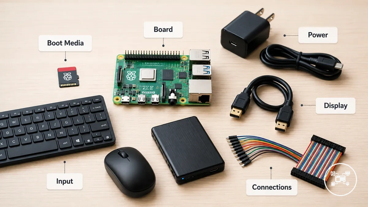
Preparing Raspberry Pi accessories requires four confirmed conditions before power is connected: board-specific compatibility, configured boot media, the required input or network connection, and a power supply rated for the selected Raspberry Pi model and attached peripherals. Raspberry Pi Documentation states that these components should be prepared and assembled before the initial power connection because an incorrect interface, absent operating system, or insufficient power allocation can prevent booting or peripheral operation.
The checklist below separates the required components from optional accessories and links each requirement to its setup effect.
The checklist below separates the required components from optional accessories and links each requirement to its setup effect. Confirm accessory compatibility before setup whenever a connector, enclosure, expansion board, or power requirement is specific to a board generation.
- Board model: Record the exact Raspberry Pi model and revision before selecting cables or expansion accessories. Raspberry Pi Documentation specifies, for example, that Raspberry Pi 4B and Raspberry Pi 5 use micro-HDMI display connections, while Raspberry Pi Zero and Zero 2 use mini-HDMI; choosing the wrong connector prevents a physical display connection.
- Boot media: Install an operating-system image on supported storage before assembly. Raspberry Pi Documentation recommends at least 32 GB for Raspberry Pi OS Full and at least 8 GB for Raspberry Pi OS Lite; it also states that SD-card capacities below 2 TB are supported, subject to older-model boot-partition limits.
- Desktop or headless controls: A desktop setup requires a compatible monitor, display cable, keyboard, and mouse, whereas a headless setup requires another computer, a network connection, and remote-access settings configured in Raspberry Pi Imager. This choice determines whether local input and display accessories must be connected for the first boot.
- Power supply: Match the supply voltage, current capability, connector, and cable to the board and peripheral load. Raspberry Pi's USB Power Delivery guidance recommends 5 V at 5 A for Raspberry Pi 5; a 5 V at 3 A supply can operate the board with lower-power peripherals but leaves less power available for USB devices.
- Accessory interfaces: Confirm that each storage device, display cable, USB peripheral, case, or expansion board uses a connector and physical layout supported by the selected board. A correct interface produces a complete mechanical and electrical connection; an unmatched HDMI size, USB format, GPIO layout, or case opening prevents installation or access.
- Connection state: Configure the boot media and attach the required display, input, storage, and network hardware before the power supply. Raspberry Pi Documentation lists the power supply last in the initial hardware sequence, making power application the transition from preparation to first boot.
For example, Raspberry Pi's USB Power Delivery guidance states that Raspberry Pi 5 limits the combined current available to its USB ports to a nominal 600 mA when a 5 V at 3 A supply is used, but raises that limit to a nominal 1.6 A when a compatible 5 V at 5 A supply is detected. The additional 1.0 A of calculated USB-current capacity can determine whether a higher-current SSD or hard drive operates reliably, so the peripheral load should be identified before selecting the supply.
Checking Raspberry Pi Accessory Compatibility Before Installation
Raspberry Pi accessory compatibility requires four matches before installation: the accessory must support the selected board model, use an available connector, remain within the board's power limits, and fit without obstructing ports or components. Raspberry Pi Documentation shows that these conditions differ by generation, so compatibility should be confirmed for the exact board and accessory combination rather than inferred from the Raspberry Pi name alone.
The checks below distinguish electrical, interface, and mechanical compatibility.
The checks below distinguish electrical, interface, and mechanical compatibility. A failed check identifies the installation effect before power is applied, such as an unavailable connection, insufficient peripheral current, or physical interference.
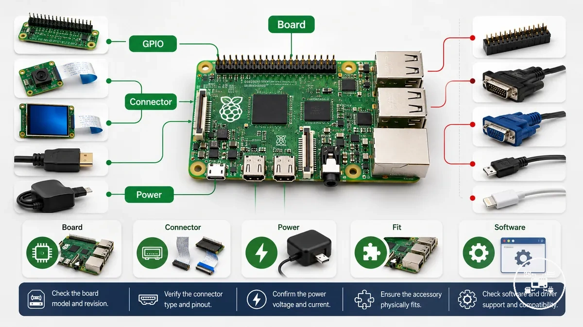
- Board model: Match the accessory's supported-model list to the exact Raspberry Pi model and revision. Raspberry Pi Documentation specifies that Raspberry Pi 4 Model B and Raspberry Pi 5 each provide two micro-HDMI outputs, whereas Raspberry Pi Zero and Zero 2 use one mini-HDMI connection; a cable made for one HDMI size does not connect directly to the other.
- Accessory interface: Match the accessory to an interface physically present on the board, such as USB Type-A, a 40-pin GPIO header, micro-HDMI, mini-HDMI, CSI, or DSI. Raspberry Pi's hardware tables show that Raspberry Pi 5 uses two combined 22-pin, 0.5 mm-pitch camera/display connectors, while flagship boards through Raspberry Pi 4 use separate standard 15-pin, 1.0 mm-pitch camera and display connectors; these accessories therefore require the cable format specified for the board.
- Power requirement: Add the accessory load to the power conditions specified for the board. Raspberry Pi Documentation lists Raspberry Pi 5 power as 5 V at 5 A (25 W), or 5 V at 3 A (15 W) with a 600 mA peripheral-current limit; an attached USB device that requires more than the available allocation needs a compatible higher-capacity supply or separate power arrangement.
- Physical fit: Check mounting-hole positions, case openings, GPIO clearance, cooler height, and cable routing against the accessory's board-specific drawings. Electrical compatibility is insufficient when an enclosure blocks a connector, a HAT contacts a cooling component, or a cable cannot reach the required socket without excessive bending.
- Software support: Confirm that the accessory manufacturer identifies a supported Raspberry Pi OS release, kernel driver, or installation package for the selected board. When no supported software condition is published, hardware fit alone does not establish that the operating system will detect or control the accessory.
For example, Raspberry Pi Documentation identifies a 40-pin GPIO header on both Raspberry Pi 4 Model B and Raspberry Pi 5, but it identifies different camera/display connectors: 15 pins at 1.0 mm pitch on Raspberry Pi 4 and 22 pins at 0.5 mm pitch on Raspberry Pi 5. A GPIO accessory may retain the same header connection while a camera or display accessory requires a different flexible cable, demonstrating why each interface must be checked independently.
A GPIO accessory may retain the same header connection while a camera or display accessory requires a different flexible cable, demonstrating why each interface must be checked independently.
These checks define whether individual Raspberry Pi accessories can be connected under the selected board's interface, power, software, and clearance conditions without implying universal compatibility.
Connecting Power and Core Raspberry Pi Accessories
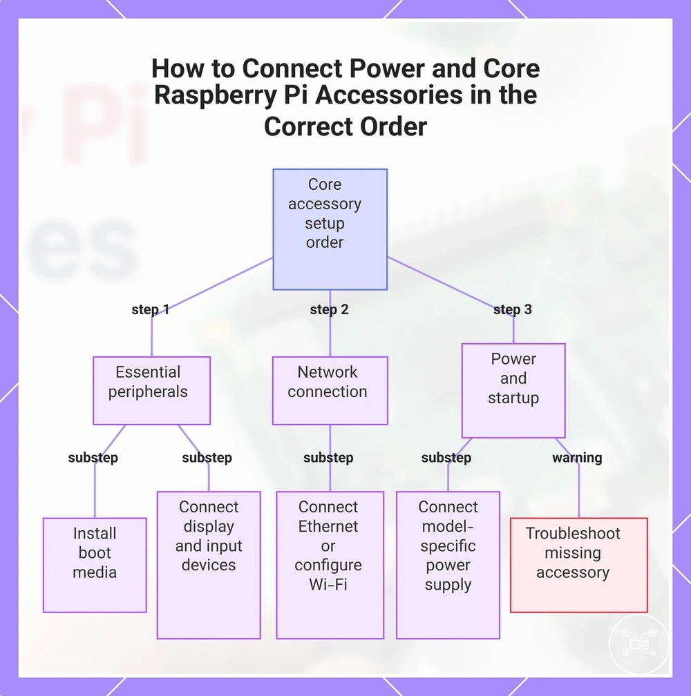
Connect core Raspberry Pi accessories in this installation order: insert the boot media, connect the display, attach input devices, connect the network if required, and connect the power supply last. According to Raspberry Pi Documentation, applying power after the required accessories are connected allows the firmware to begin booting with the intended hardware configuration and reduces unnecessary reconnections during the initial setup.
The required power connection depends on the Raspberry Pi model.
The required power connection depends on the Raspberry Pi model. Raspberry Pi Documentation specifies that Raspberry Pi 5 is designed for a 5 V, 5 A (25 W) USB Power Delivery power supply for full peripheral capability, while Raspberry Pi 4 Model B officially recommends a 5 V, 3 A (15 W) USB-C power supply under its supported operating conditions.
- Insert the boot media: Install the prepared microSD card or another supported boot device completely before applying power so the firmware can locate the operating system during startup.
- Connect the display cable: Attach the correct HDMI cable for the board model. According to Raspberry Pi Documentation, Raspberry Pi 4 Model B and Raspberry Pi 5 use micro-HDMI outputs, whereas Raspberry Pi Zero and Raspberry Pi Zero 2 W use a mini-HDMI connector.
- Attach input devices: Connect a USB keyboard and mouse before the first boot for a desktop installation. If a headless installation has already been configured with Raspberry Pi Imager, connect the required network interface instead of local input devices.
- Connect network hardware: Attach an Ethernet cable before powering the board when using a wired connection. If supported Wi-Fi credentials have already been configured, compatible wireless Raspberry Pi models can complete the initial setup without Ethernet.
- Connect the power supply: Connect the official or compatible power supply only after the previous accessories have been attached. Supplying power immediately starts the boot sequence and begins hardware detection.
- Verify the startup state: Confirm that the power LED is illuminated, the activity LED indicates storage access where applicable, and the display or remote connection reaches the operating system. If an essential accessory is not detected, disconnect the power before reconnecting or replacing hardware.
For example, Raspberry Pi Documentation states that Raspberry Pi 5 supplied by a compatible 5 V, 5 A (25 W) USB Power Delivery adapter can increase the default USB peripheral current limit from approximately 600 mA to approximately 1.6 A when the higher-current mode is available. This additional current capacity supports higher-power USB accessories, such as external SSDs, without requiring separately powered USB hubs.
This additional current capacity supports higher-power USB accessories, such as external SSDs, without requiring separately powered USB hubs.
After confirming a successful startup, follow the board-specific requirements in the dedicated power accessory setup guide when selecting compatible power supplies, cables, and power-related accessories for your Raspberry Pi model.
This chart shows the recommended installation order for connecting core accessories to a Raspberry Pi before applying power, including the required steps for a successful startup.
This chart shows the recommended installation order for connecting core accessories to a Raspberry Pi before applying power, including the required steps for a successful startup.
Setting Up Storage, Display, and Cable Accessories
Raspberry Pi storage, display, and cable accessories should be connected in a defined order: prepare the boot storage, connect storage devices and display cables to the correct interfaces, verify that every connector is fully seated, and connect the power supply only after the required accessories are installed. According to Raspberry Pi Documentation, the boot device must contain a valid operating system before startup, and hardware should be connected before power is applied so the firmware can detect attached devices during the boot sequence.
The required connectors depend on the Raspberry Pi model.
The required connectors depend on the Raspberry Pi model. Raspberry Pi Documentation specifies that Raspberry Pi 4 Model B and Raspberry Pi 5 provide 2 micro-HDMI ports, 2 USB 3.0 ports, and 2 USB 2.0 ports, while Raspberry Pi Zero and Raspberry Pi Zero 2 W use a single mini-HDMI connector and a micro-USB OTG interface. Matching the storage device, display cable, and connector type to the selected board prevents installation failures caused by incompatible interfaces.
- Prepare the boot storage: Write Raspberry Pi OS or another supported operating system to a microSD card or another supported boot device before installation. Raspberry Pi Documentation identifies microSD as the standard boot medium for all Raspberry Pi models, while Raspberry Pi 5 also supports NVMe SSD boot through a compatible PCIe connection after appropriate firmware support is enabled.
- Connect storage accessories: Insert the microSD card fully into its slot or connect supported external storage before startup. External USB storage should be connected to a USB port that matches its interface. According to Raspberry Pi Documentation, USB 3 devices remain compatible with USB 2 ports but operate at USB 2 transfer speeds when connected through that interface.
- Connect the display cable: Attach the display before applying power using the connector required by the board model. Raspberry Pi 4 Model B and Raspberry Pi 5 require micro-HDMI cables or adapters, whereas Raspberry Pi Zero models require a mini-HDMI cable or adapter.
- Check cable installation: Ensure every cable is fully inserted without excessive bending or tension. Storage, HDMI, USB, and ribbon cables should follow their keyed orientation because partially seated connectors can prevent storage detection or video output during boot.
- Verify successful detection: After startup, confirm that the operating system loads from the selected boot device, the display produces video output, and connected storage devices appear in the operating system. If a storage device or display is not detected, Raspberry Pi Documentation recommends shutting the board down safely before disconnecting or reconnecting hardware.
For example, according to Raspberry Pi Documentation, Raspberry Pi 5 provides 2 USB 3.0 ports operating at up to 5 Gbit/s under the USB 3.0 specification, while its 2 USB 2.0 ports operate at up to 480 Mbit/s. Connecting an external SSD to a USB 3.0 port instead of a USB 2.0 port allows the storage device to use the higher-speed interface when the SSD also supports USB 3.0.
For board-specific boot media and external storage configuration, continue to the storage accessory setup guide.
For board-specific boot media and external storage configuration, continue to the storage accessory setup guide. If you need connector, monitor, or cable installation details, refer to the dedicated display and cable setup guide.
If you need connector, monitor, or cable installation details, refer to the dedicated display and cable setup guide.
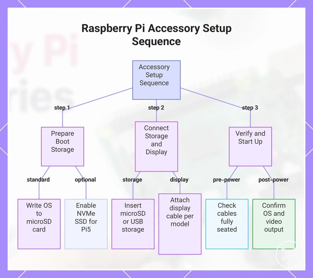
This chart shows the recommended order for preparing boot storage, connecting storage and display accessories, and verifying the setup before and after applying power.
Installing Cooling and GPIO Accessories
Install Raspberry Pi cooling and GPIO accessories while the board is powered off: mount the cooling component with unobstructed airflow, connect any fan to its specified power header, align GPIO accessories with the correct header pins, and confirm that expansion hardware clears nearby connectors and cables. The installation is complete only when the cooling accessory has secure thermal contact or airflow access and the GPIO accessory is fully seated without offset pins or mechanical interference.
Cooling and GPIO connection points differ by board and accessory type.
Cooling and GPIO connection points differ by board and accessory type. Raspberry Pi Documentation specifies that Raspberry Pi 5 has a 40-pin GPIO header and a separate 4-pin JST-SH PWM fan connector positioned between the GPIO header and the USB 2.0 ports; a cooling fan designed for that connector should not occupy general-purpose GPIO pins.
- Mount the cooling component: Place a heatsink or active cooler on the processor area identified by its installation instructions, using the supplied thermal interface material and mounting points. Full contact supports heat transfer, while a tilted heatsink or protective film left on the thermal pad creates an incomplete thermal path.
- Preserve the airflow path: Keep fan inlets, outlets, and case vents clear of ribbon cables, HATs, and enclosure panels. If an expansion board covers the cooler area or restricts the fan opening, use the spacing or cooling arrangement specified for that board-and-accessory combination.
- Connect the cooling fan: Insert the fan plug into the dedicated connector specified for the Raspberry Pi model, following the keyed orientation. Raspberry Pi Documentation states that both Raspberry Pi 5 fan options connect to the board’s 4-pin JST-SH PWM fan connector, which enables controlled fan operation without using the 40-pin GPIO header.
- Align the GPIO accessory: Match pin 1 on the GPIO accessory with pin 1 on the Raspberry Pi header, then press the connector down evenly across both rows. A one-pin offset leaves the accessory connected to unintended power or signal pins, so the header must show no exposed row at either end unless the accessory documentation explicitly specifies a partial connection.
- Check expansion clearance: Confirm that the GPIO accessory, spacers, fan, heatsink, case, and ribbon cables occupy separate physical paths. Raspberry Pi Documentation identifies the Raspberry Pi 5 fan connector beside the 40-pin header, so a HAT or expansion board must provide enough clearance for the fan plug and cable where both accessories are installed.
- Verify after startup: Apply power only after the mechanical and electrical checks are complete. Confirm that the fan responds under its supported control configuration and that the GPIO accessory is recognised by its required driver, library, or application; power the board down before correcting a misplaced connector.
For example, Raspberry Pi Documentation lists two distinct Raspberry Pi 5 connections: the 40-pin GPIO header for compatible expansion hardware and the 4-pin JST-SH PWM connector for supported cooling fans. Installing a HAT on the 40-pin header while routing the fan cable to the separate 4-pin connector preserves both interfaces, provided the HAT, spacers, and enclosure leave physical clearance around the fan plug.
For example, Raspberry Pi Documentation lists two distinct Raspberry Pi 5 connections: the 40-pin GPIO header for compatible expansion hardware and the 4-pin JST-SH PWM connector for supported cooling fans.
Use the dedicated cooling accessory installation guidance when cooler mounting or airflow requirements differ by enclosure, and follow the GPIO accessory setup guidance for accessory-specific pin functions, software requirements, and expansion connections.
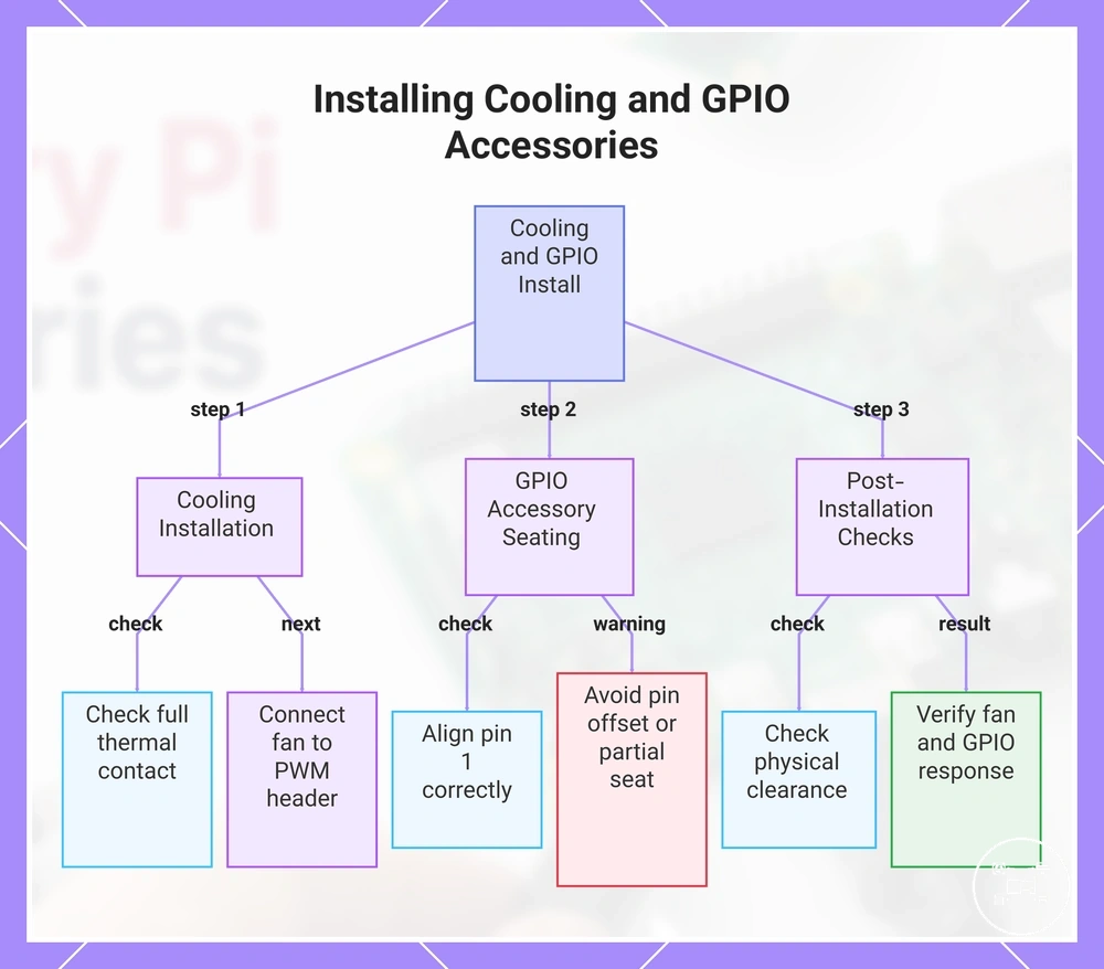
This chart shows the main steps and checks for installing cooling and GPIO accessories on a Raspberry Pi, including mounting, alignment, and post-installation verification.
This chart shows the main steps and checks for installing cooling and GPIO accessories on a Raspberry Pi, including mounting, alignment, and post-installation verification.
Avoiding Common Raspberry Pi Accessory Setup Mistakes
Common Raspberry Pi accessory setup mistakes fall into three diagnostic categories: incompatible hardware, incomplete physical connections, and unsupported power or software configurations. Check each problem as mistake → likely cause → observable symptom → corrective action, because the same symptom can have more than one cause and no single correction applies to every Raspberry Pi model or accessory.
The checklist below covers accessory-level checks only.
The checklist below covers accessory-level checks only. Raspberry Pi Documentation identifies board-specific interfaces and power limits, including 5 V at 5 A (25 W) for Raspberry Pi 5, or 5 V at 3 A (15 W) with a 600 mA peripheral-current limit; these model-specific conditions help distinguish a setup error from an accessory fault.
- Mistake: incompatible board or connector. Likely cause: The accessory targets another Raspberry Pi model, port format, or header layout. Symptom or risk: The connector does not fit, the accessory cannot be seated, or the operating system does not detect it. Corrective action: Compare the accessory’s supported-model list and connector specification with the exact board revision before reconnecting it.
- Mistake: insufficient peripheral power. Likely cause: The supply or configuration leaves less current available than the connected USB accessories require. Symptom or risk: A storage device disconnects, a peripheral resets, or the system reports an undervoltage condition. Corrective action: For Raspberry Pi 5, use the documented 5 V, 5 A (25 W) supply condition when the attached peripheral load exceeds the 600 mA limit associated with a 5 V, 3 A supply.
- Mistake: loose or incorrectly oriented connection. Likely cause: An HDMI, USB, ribbon, storage, fan, or GPIO connector is only partly seated or is inserted in the wrong orientation. Symptom or risk: The display remains blank, storage is absent, a fan does not respond, or a GPIO accessory connects to unintended pins. Corrective action: Shut the Raspberry Pi down, disconnect power, inspect connector orientation, and reseat the affected connection without applying sideways force.
- Mistake: offset GPIO installation. Likely cause: A HAT or expansion connector is shifted by one or more positions on the 40-pin GPIO header. Symptom or risk: The accessory receives unintended power or signal connections and may fail to initialise. Corrective action: Align pin 1 on the accessory with pin 1 on the Raspberry Pi header and confirm that both rows are evenly seated before restoring power.
- Mistake: unsupported software configuration. Likely cause: The installed Raspberry Pi OS release lacks the required driver, overlay, firmware, library, or accessory configuration. Symptom or risk: The hardware is physically connected but does not appear in the operating system or application. Corrective action: Check the accessory manufacturer’s supported Raspberry Pi OS version and apply only the specified software or configuration requirements.
- Mistake: obstructed cooling or expansion clearance. Likely cause: A cable, case panel, HAT, or storage adapter blocks a fan opening, presses against a heatsink, or occupies the same physical space as another accessory. Symptom or risk: The fan cannot move air freely, connectors are strained, or the expansion board cannot sit level. Corrective action: Re-route cables and verify the combined cooler, spacer, enclosure, and expansion-board clearances before powering the system.
For example, Raspberry Pi Documentation identifies separate connections on Raspberry Pi 5: a 40-pin GPIO header for expansion hardware and a 4-pin JST-SH PWM fan connector for supported cooling fans. Connecting the fan to the dedicated four-pin socket instead of the GPIO header preserves the expansion interface and removes one possible source of incorrect pin assignment.
Connecting the fan to the dedicated four-pin socket instead of the GPIO header preserves the expansion interface and removes one possible source of incorrect pin assignment.
If these accessory-level checks do not isolate the cause, continue with troubleshooting setup problems for broader diagnosis of boot media, firmware, operating system, power delivery, and board-level symptoms.
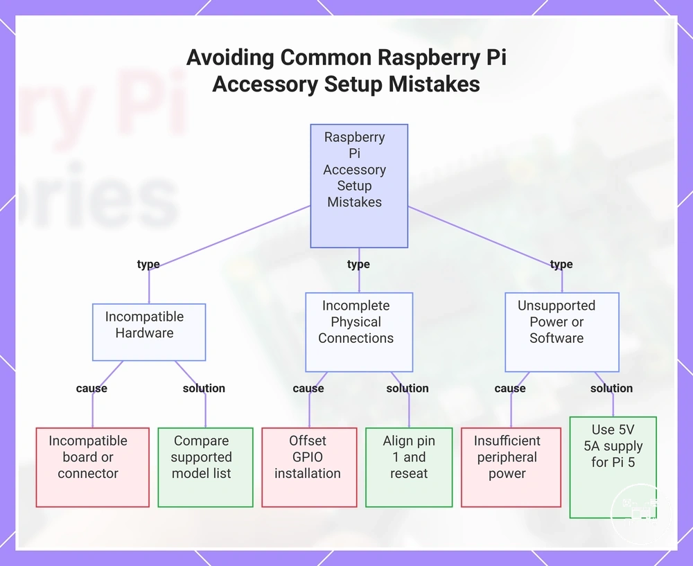
This chart groups common Raspberry Pi accessory setup mistakes into three diagnostic categories and shows a typical mistake and its corrective action for each category.
This chart groups common Raspberry Pi accessory setup mistakes into three diagnostic categories and shows a typical mistake and its corrective action for each category.